11. Program - Road
The road program can use a curve composed of straight lines, circular curves, or transition curves as a reference for measurement and layout. The program calculates and sets out the coordinates of design points based on the pile numbers and deviations determined by road design.
Road program menu

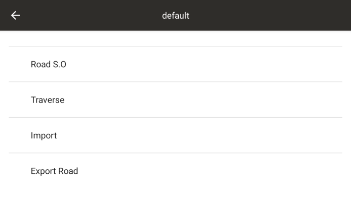
11.1 Road selection
Select a road as the current road, each road consisting of two parts: vertical alignment and horizontal alignment
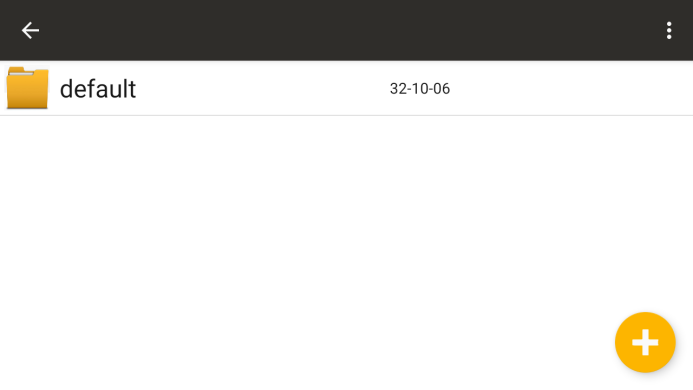
◆ [+]: New road construction project
The function keys in the upper right corner can be used for editing and deleting functions; Long press the engineering file to delete it as well
11.2 Horizontal Alignment
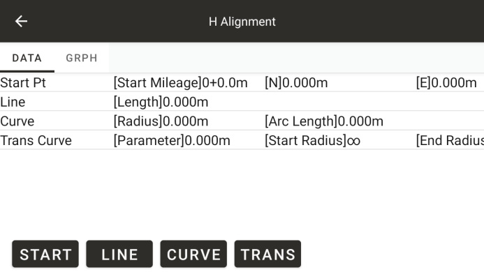
◆: Form a flat shape of the road based on the input horizontal alignment data
The horizontal alignment includes the following elements: starting point, straight line, circular curve, and transition curve
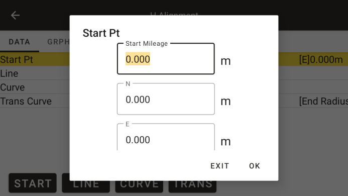
◆ Starting mileage: the mileage at the starting point
◆ N: Coordinates of the starting point N
◆ E: Coordinates of the starting point E
◆ Azimuth: Starting azimuth
● Input straight line parameters
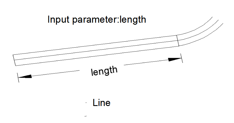
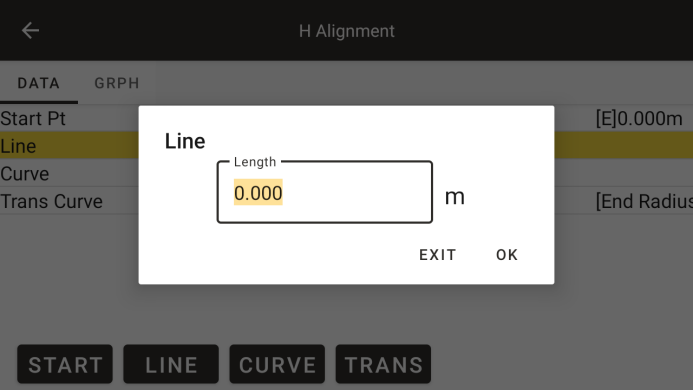
◆ Line: Enter the parameters of the line
◆ Length: Enter the length of the line, which should be greater than zero
● Input circular curve parameters
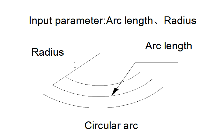
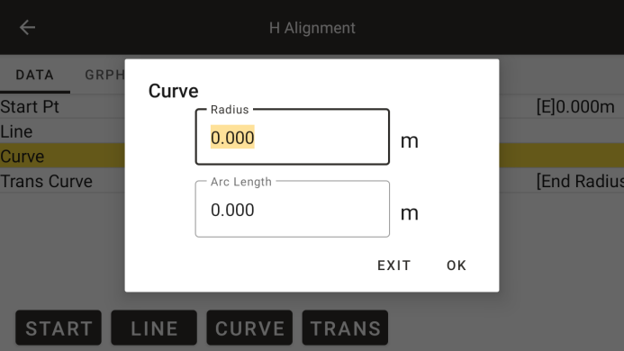
◆ Radius: Enter the radius of the circular curve, positive numbers indicate right turns, negative numbers indicate left turns
◆ Radiance: Enter the arc length of the circular curve, which must be a positive value
● Input transition curve parameters
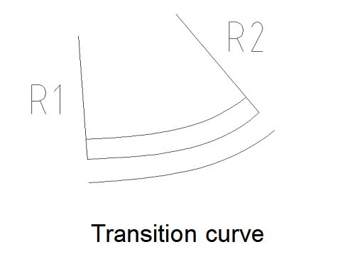
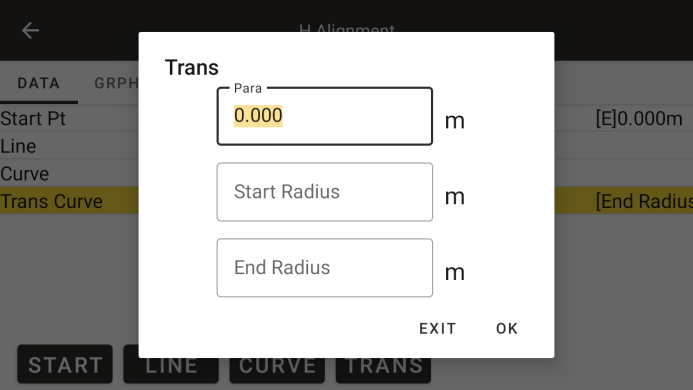
◆ Parameters: Enter the transition curve parameter A, where a positive number indicates a right turn and a negative number indicates a left turn
◆ Starting radius: Enter the starting radius Rs of the transition curve, which can only be a positive number. When the input radius is ∞, for ease of input, simply enter a radius of 0.
◆ End radius: Enter the end radius Re of the transition curve, which can only be a positive number. When the input radius is ∞, for ease of input, simply enter the radius as 0.
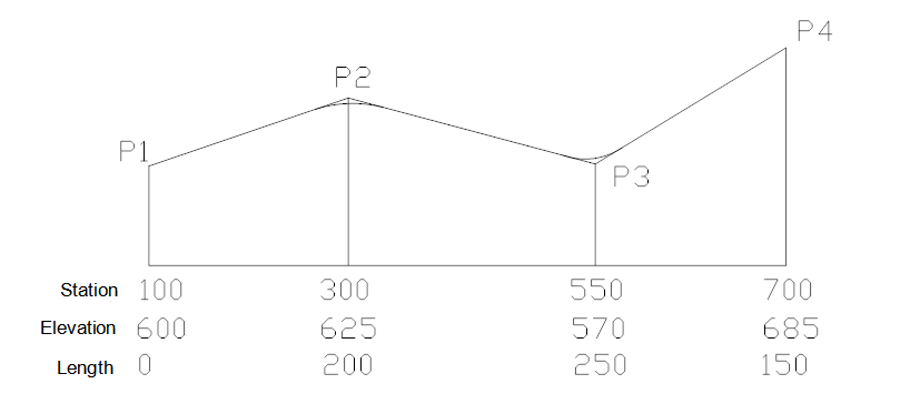
11.3 Vertical Alignment
The vertical alignment consists of a set of intersecting points, including station number, elevation, and curve length. The starting and ending curve lengths of the vertical alignment must be zero.
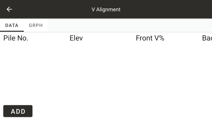
◆ [Add]: Add a vertical alignment data
◆: Display the longitudinal profile of the road based on the alignment data
● Vertical alignment graphics
The names in the graph are numbered in the order of the alignment data
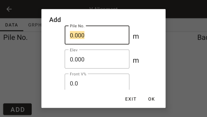
◆ Station number: Slope change point station number
◆ Elevation: Slope change point elevation
Front slope gradient: the slope between the current point and the previous point
◆ Back slope gradient: the slope between the current point and the next point
◆ Radius: Distance between adjacent points
11.4 Road layout
For road alignment and layout, it is necessary to first define the line shape. Define horizontal and vertical alignment data according to the methods in the previous sections (if vertical alignment data does not require calculation of fill and excavation, it can be left undefined).
Before road layout, station construction must be carried out
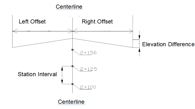
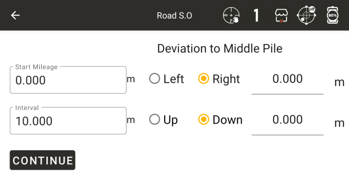
◆ Starting mileage: the starting position for continuous layout
Step value: The mileage value increased or decreased each time during the layout process
◆ Left, right: The deviation from the center point of the road to the left and right, perpendicular to the road
◆ Up and down: elevation difference between the layout point and the design point on the centerline of the road
◆ [Continue]: Complete preliminary settings and start entering the layout interface
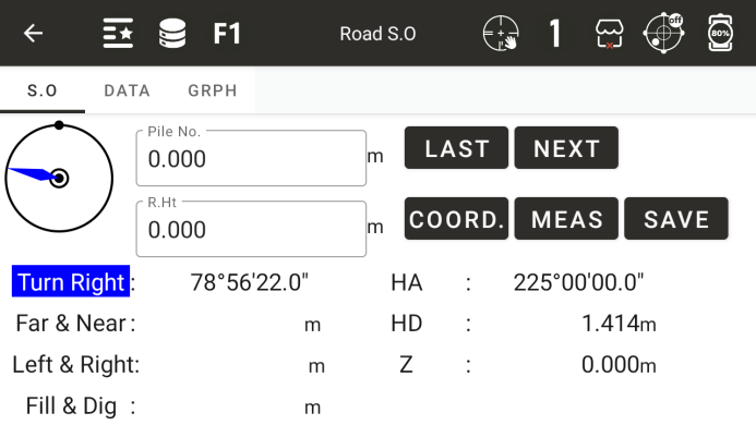
◆ Station number: The station number of the current layout point
◆ Mirror height: Current prism height
◆ Upper point: The previous point of the current layout point
◆ Next point: The next point of the current layout point
◆ Correct: The current value is the correct value
Turn left or right: The angle at which the instrument should rotate horizontally to the left or right
◆ Move closer or farther: The distance at which a prism moves closer or farther relative to an instrument
◆ Right or left: the distance the prism moves to the left or right
Excavation and filling: the distance that the prism moves upwards or downwards
◆ Horizontal angle: Input the horizontal angle of the layout
◆ Horizontal distance: Input the horizontal distance of the layout
◆ Height: The elevation of the layout point
◆ [Storage]: Store the previous measurement value
◆ [Measurement]: Conduct measurements
◆: Display the measurement results
◆: Display the graphical relationship between layout points, survey stations, and survey points
11.5 Coordinate Calculation
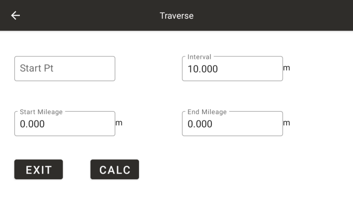
Enter the starting mileage, ending mileage, step value, and starting point name, click [Calculate], and after successful calculation, the page will automatically exit
11.6 Importing Roads
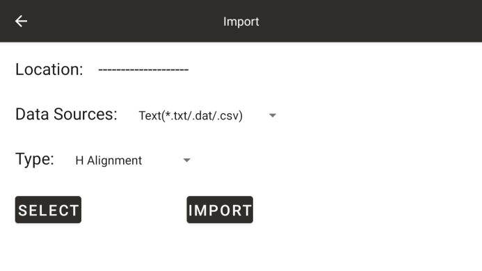
◆ Data type: Select the imported data type as horizontal or vertical alignment
◆ [File Selection]: Select the imported file from the system memory
◆ [Import]: Import roads
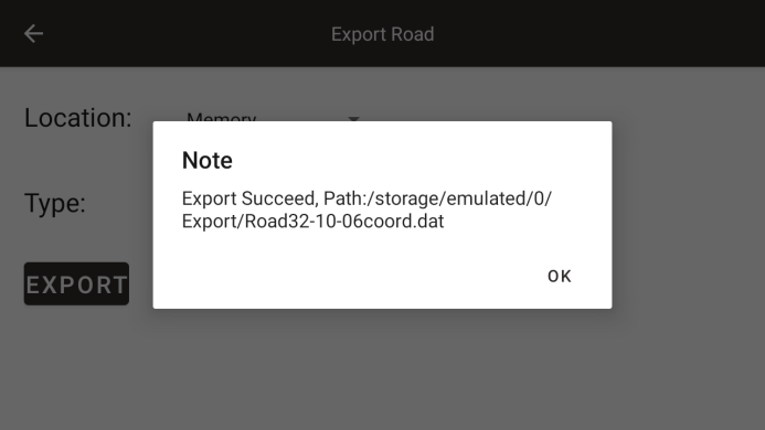
11.7 Exporting Roads
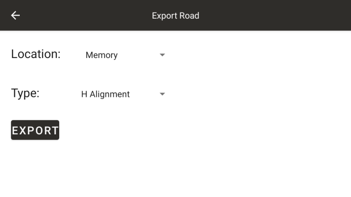
◆ Export location: Select the road export location as memory, serial port, or USB drive
◆ Data type: Select the exported data type as horizontal or vertical alignment
◆ [Export]: Export the roads in the current project. Click to open a dialog box where you can set the file name for the export
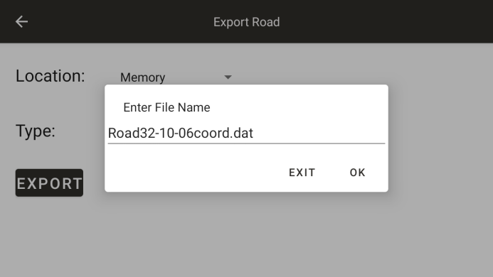
After clicking OK, a prompt will pop up indicating whether the export was successful and the export path