8. Layout
● Station setting should be carried out before layout
Layout interface menu

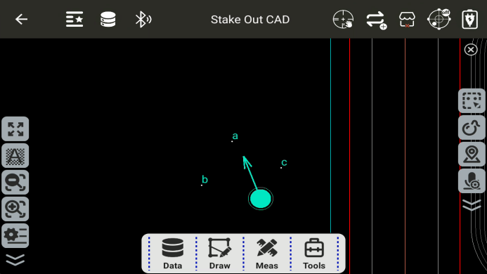
8.1 Stake Out CAD
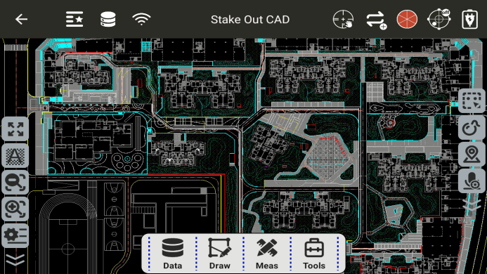
Enter the CAD stakeout program
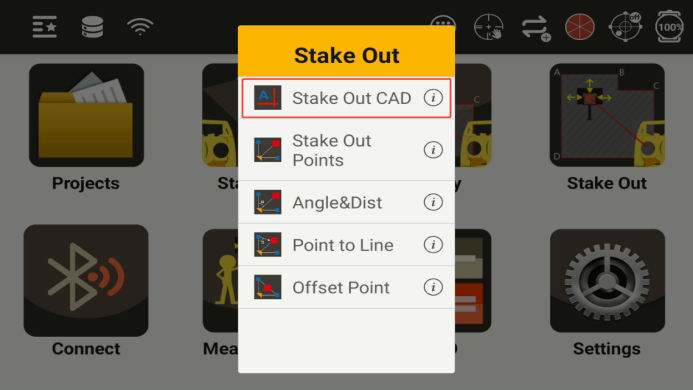
You can import CAD base map files (dxf/dwg) and select points in the drawing for layout.
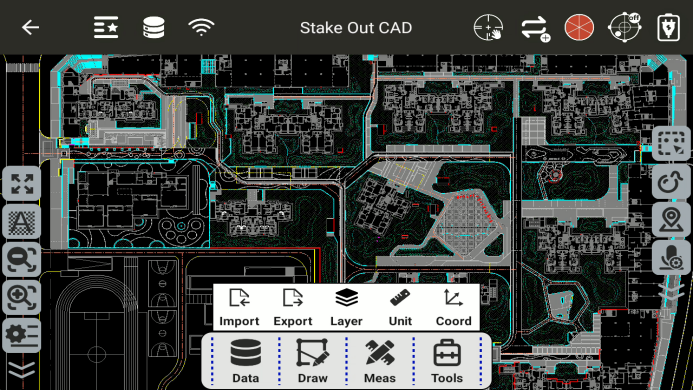
Import: Imports the CAD base file.
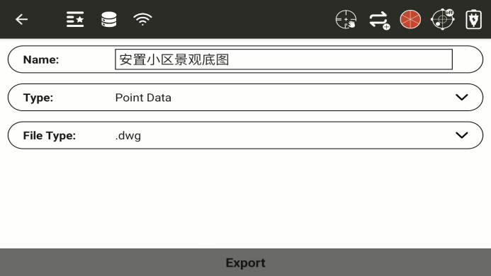
Export: Exports the CAD base file.
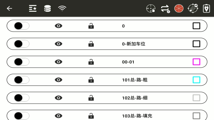
Layers: Displays all layers of the imported CAD document; you can choose whether to display layer information.
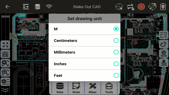
Drawing Units: Sets the unit of the CAD drawing. If the original unit of the drawing data is meters (m), for example, the N coordinate of a point is 123321.1233m, and you set the drawing unit to cm, then the coordinate of that point will be 12332112.33**m, resulting in a significant difference in the drawing data. Therefore, after importing the drawing, you need to ensure that the drawing unit is consistent with the original unit of the drawing.
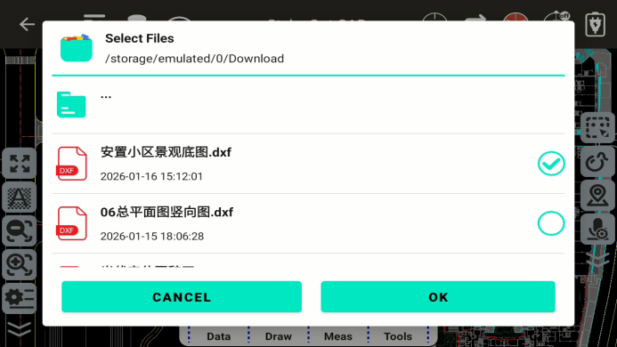
Import CAD drawings: After clicking Import, select the drawing path, select the drawing file, and click OK.
Export CAD drawings: After clicking export, enter the export interface, enter the drawing name, select the data type and file type to export (dxf, dwg optional), and click export.
Layers: You can view the layer information of the CAD base map.
◆
![]() : Unfreeze/freeze layer;
: Unfreeze/freeze layer;
◆
![]() : Turn layer on/off;
: Turn layer on/off;
◆
![]() : Lock/unlock layer;
: Lock/unlock layer;
Set drawing units: Click on drawing units, select the actual units of the drawing, and the set units must be consistent with the original units of the drawing.
Drawing: The drawing module has four functions: point drawing, polyline drawing, arc drawing, and polygon drawing.
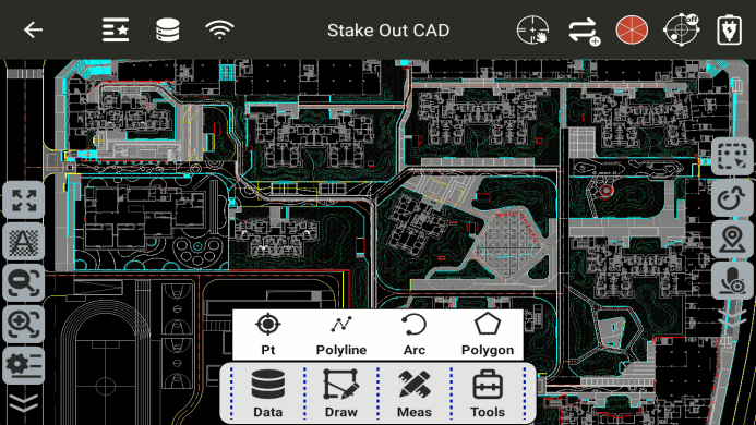
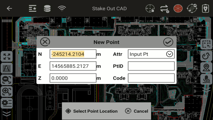
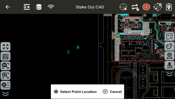
Point drawing: Select the location of the point and draw the point.
Polyline drawing: You can select the target point element by selecting from the list or by snapping to draw a polyline.

Arc drawing: The target point element can be selected by selecting from a list or by snapping;
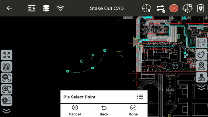
Note: When drawing an arc, selecting points clockwise and counterclockwise will result in different arcs;
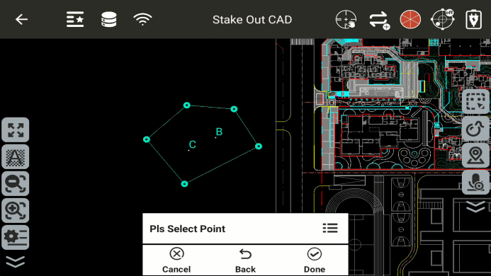
Polygon drawing: Target point elements can be selected by list selection or snapping. Points can be selected clockwise or counterclockwise to draw non-intersecting polygons;
Measurement: The measurement module has three functions: angle measurement, distance measurement, and area measurement.
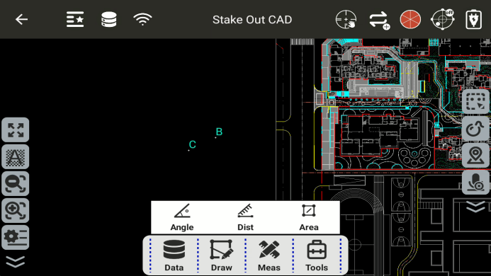
Angle measurement: Select three points, and take the second point as the angle point.


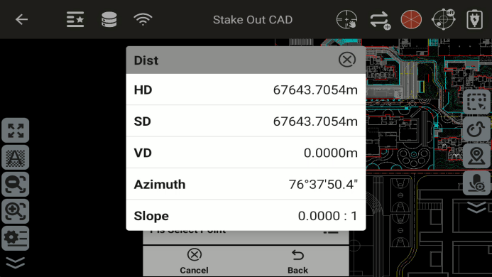
Distance measurement: Select two points and calculate the distance between them, azimuth angle, and other information.
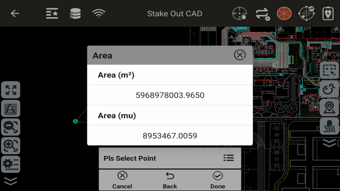
Area measurement: Select points clockwise or counterclockwise and calculate the area of the enclosed region.

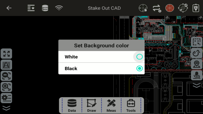
Tools: The module has four functions: background setting, calculator, three-point circle determination, and point-line inverse calculation.

Background: You can choose the background color of the CAD layout interface; you can choose black or white.
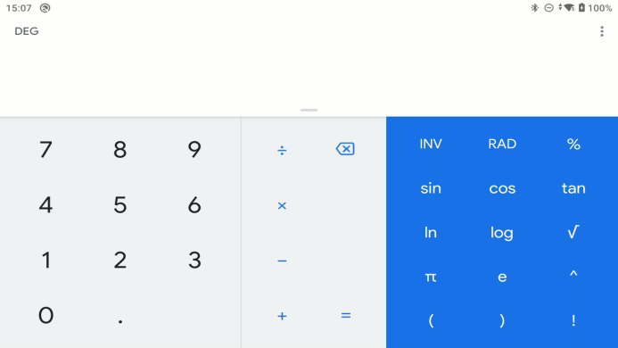
Calculator: Click to enter the calculator interface.
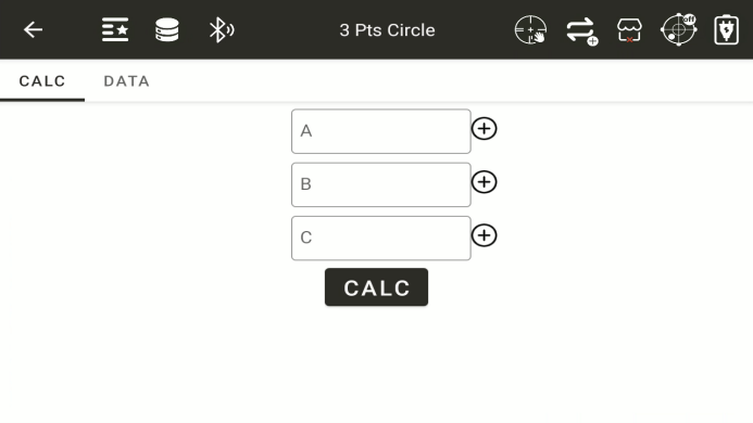
Three-point circle determination: After clicking, you will enter the three-point circle determination function interface. Select three points to determine a circle.
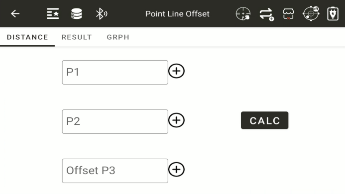
Point-to-Line Inverse Calculation: Computes the perpendicular offset distance from a given point to a defined line.
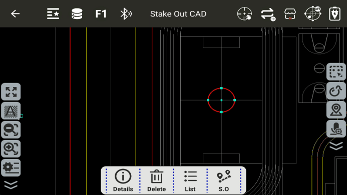
Point Stakeout:
click
![]() on the screen, then move the arrow to point to the target stakeout location.
on the screen, then move the arrow to point to the target stakeout location.
![]() : Automatic Instrument Orientation to Stakeout Point.
: Automatic Instrument Orientation to Stakeout Point.
![]() : After aiming at the target prism, click this button to start measurement. For tracking measurement, set the cooperative target to the prism, automation to "Lock," and measurement mode to "Tracking."
: After aiming at the target prism, click this button to start measurement. For tracking measurement, set the cooperative target to the prism, automation to "Lock," and measurement mode to "Tracking."
![]() : Once the prism is positioned at the stakeout point, click this button to save the point.
: Once the prism is positioned at the stakeout point, click this button to save the point.
![]() : Prism Height (Target Elevation)
: Prism Height (Target Elevation)
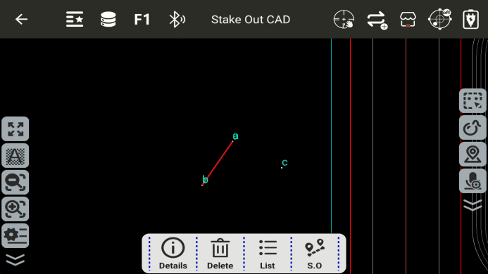
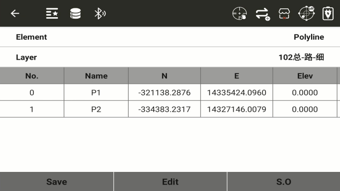
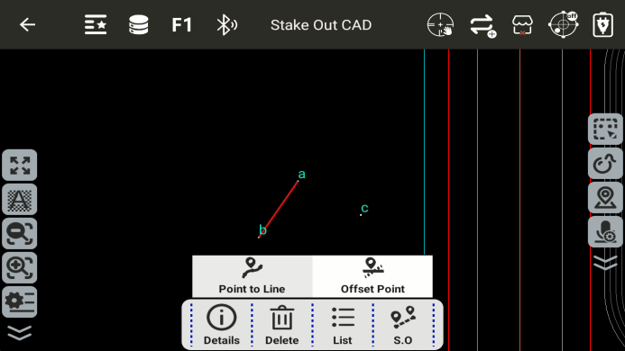
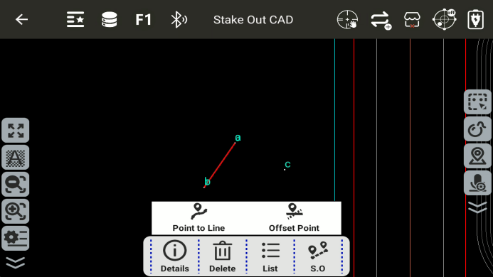
**Line Stakeout:**Select a line element to choose either line stakeout or point-on-line stakeout. The two endpoints of the line can be viewed.
Point to line:
Key-Point Stakeout: Stake out the two endpoints of the selected line.
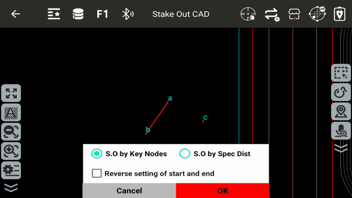

![]() and
and
![]() : Switch Between Different Line Endpoints.
: Switch Between Different Line Endpoints.
Stakeout by Specified Distance: Set an offset value in the given direction to stake out the point.
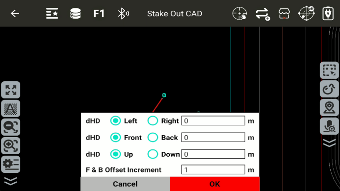

Forward/Backward Offset Increment: Set the interval between adjacent stakeout points along the defined line direction.
![]() and
and
![]() : Switch between stakeout points.
: Switch between stakeout points.
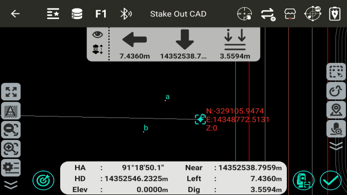
Line Stakeout
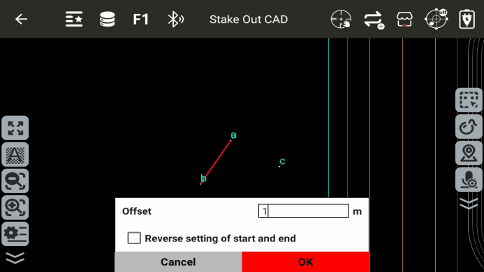
Offset: Perpendicular to the line, from the start point toward the end point; left is negative, right is positive.
Arc Stakeout
Stakeout by Specified Distance
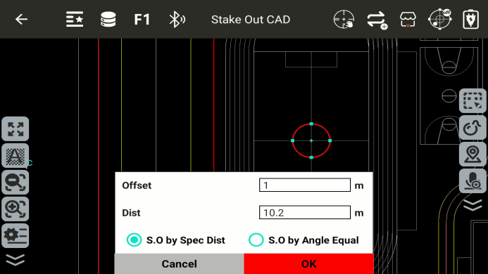

Offset: The stakeout arc is concentric with the defined reference arc. The offset is the distance between the two arcs. A positive offset increases the radius of the stakeout arc, while a negative offset decreases it.
Distance: Defines the spacing between stakeout points along the arc.
![]() and
and
![]() : Switch between stakeout points.
: Switch between stakeout points.
Stakeout by Equal Angle Division
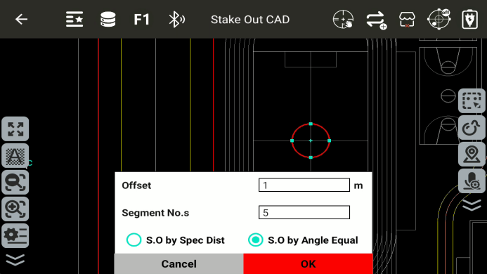
Offset: The stakeout arc is concentric with the defined reference arc. The offset is the distance between the two arcs. A positive offset increases the radius of the stakeout arc, while a negative offset decreases it.
Number of Segments: Divides the arc into the specified number of points, including the start and end points. For example, if the number of segments is 5, the arc is divided into 4 segments.
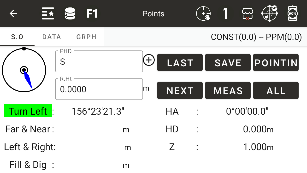
8.2 Stake Out Points
By selecting a target point, the system determines the target location based on the direction, horizontal distance, and height difference relative to the target point.
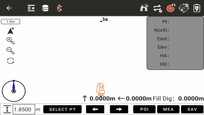
This is the main interface of Point Stakeout.
![]() : Indicates the current screen scale.
: Indicates the current screen scale.
![]() : Indicates the current device orientation.
: Indicates the current device orientation.
![]() : Allows input of the current prism height.
: Allows input of the current prism height.
![]() : Allows selection of the current stakeout point.
: Allows selection of the current stakeout point.
- Tap to enter the Stakeout Point Library.
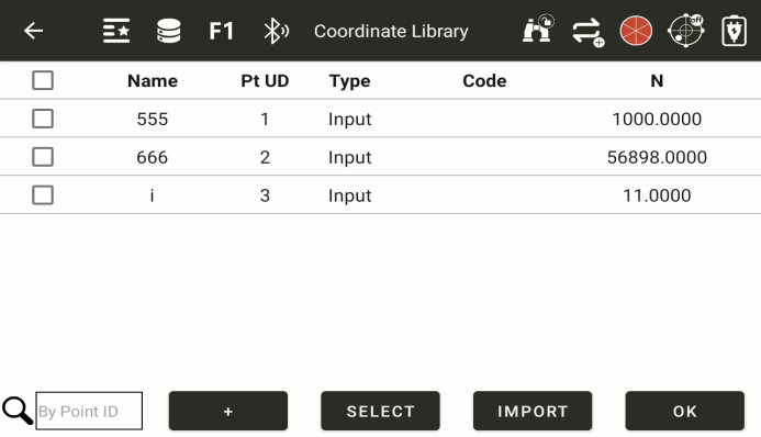
Allows selection of the corresponding stakeout point.
![]() : Filter points using the entered keyword.
: Filter points using the entered keyword.
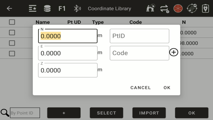
![]() : Points can also be entered manually.
: Points can also be entered manually.
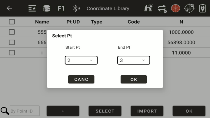
![]() : Allows quick batch selection of points from the point library.
: Allows quick batch selection of points from the point library.
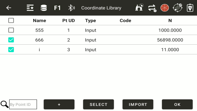
![]() : Allows batch import of points.
: Allows batch import of points.
![]() : After selecting stakeout points, return to the Point Stakeout interface.
: After selecting stakeout points, return to the Point Stakeout interface.
![]() : Indicates the direction of the current backsight point.
: Indicates the direction of the current backsight point.
![]() : Measure the current point; the icon changes to
: Measure the current point; the icon changes to
![]() to allow saving the point.
to allow saving the point.
![]() : Save the current measured point.
: Save the current measured point.
-
Pt:Displays the name of the current stakeout point.
-
North/South:Displays the North/South coordinate of the current stakeout point.
-
East/West:Displays the East/West coordinate of the current stakeout point.
-
Elev:Displays the elevation of the current stakeout point.
-
HA:Displays the horizontal angle of the current stakeout point.
-
HD:Displays the horizontal distance to the current stakeout point.
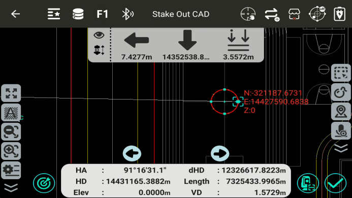
![]() : Distance to move the prism forward or backward.
: Distance to move the prism forward or backward.
![]() : Distance to move the prism left or right.
: Distance to move the prism left or right.
![]() : Distance to move the prism up or down.
: Distance to move the prism up or down.
8.3 Angle & distance
● Conduct layout by inputting the distance, angle, and elevation values between the measurement station and the point to be surveyed
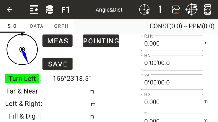
◆ Mirror height: Current prism height
◆ Correct: The current value is the correct value
Turn left or right: The angle at which the instrument should rotate horizontally to the left or right
◆ Move closer or farther: The distance at which a prism moves closer or farther relative to an instrument
◆ Right or left: the distance the prism moves to the left or right
◆ Excavation and filling: the distance that the prism moves upwards or downwards
◆ Horizontal angle: Input the horizontal angle of the layout
◆ Vertical angle: Enter the vertical angle of the layout
◆ Horizontal distance: Input the horizontal distance of the layout
◆ Height: The elevation of the layout point
◆ [Storage]: Store the previous measurement value
◆ [Measurement]: Conduct measurements
◆: Display the measurement results
◆: Display the graphical relationship between layout points, survey stations, and survey points
8.4 Direction Line Layout
Obtain the coordinates of a layout point for layout by inputting the azimuth, horizontal distance, and elevation difference of a known point
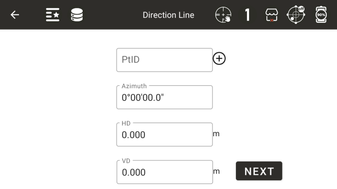
Name calling: Input or call a point as a known point
◆ Azimuth: The azimuth angle from a known point to the point to be laid out
◆ Horizontal distance: The horizontal distance between the point to be laid out and the known point
◆ Height difference: the height difference between the point to be laid out and the known point
◆ [Next]: Complete the input and proceed to the next step of the layout operation
◆ [Previous]: Return to the input interface in the previous step
● Other instructions in point layout
8.5 Line layout
Calculate the coordinates of the point to be laid out by taking two known points and inputting three deviation distances from the line formed by these two points
◆ Starting point: Input or call a known point as the starting point
◆ End point: Input or call a known point as the end point
◆ Left and Right: The distance of deviation to the left or right
◆ Front and back: the distance of deviation forward or backward
◆ Up and down: the distance of upward or downward deviation
◆ [Next]: Calculate the coordinates of the layout point based on the input above and enter the next layout interface
◆ [Previous]: Return to the input interface in the previous step
● Other instructions in point layout