15. Calibration of instruments
This instrument has undergone rigorous inspection and calibration before leaving the factory, and meets the quality requirements. However, the internal structure of the instrument may be affected by long-distance transportation or environmental changes. Therefore, both newly purchased instruments and those arriving at the testing area should undergo various inspections and calibrations in this section before operation to ensure the accuracy of the operation results.
15.1 Circular level
Inspection
After the calibration of the long level is correct, if the bubble of the round level is also centered, there is no need to calibrate it.
correcting
If the bubble is not centered, use a correction needle or an Allen wrench to adjust the correction screw below the bubble to center it. When calibrating, first loosen the calibration screws (1 or 2) opposite the direction of the bubble offset, and then tighten the remaining calibration screws in the offset direction to center the bubble. When the bubble is centered, the tightening force of the three correction screws should be consistent.
15.2 Zero point error calibration of tilt sensor
● Correction of dual axis compensation
Firstly, check the principal's leveling bubble, then use the long leveling bubble to level it, and then click the zero button to perform the zero setting operation
● Aim at the same target in the distance on the left and right sides of the disk, and follow the prompts to set it up
15.3 Telescope reticle
Inspection
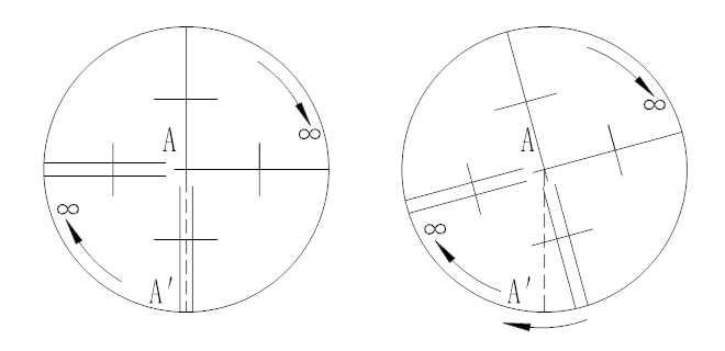
After leveling the instrument, select a target point A in the line of sight of the telescope, use the crosshair center of the reticle to aim at A, and fix the horizontal and vertical brake handwheels.
Rotate the telescope vertically and micro rotate the handwheel to move point A to the edge of the field of view (point A ').
If point A is moving along the vertical axis of the crosshair, i.e. point A 'is still within the vertical axis, then the crosshair does not tilt and does not need to be corrected.
As shown in the figure, if point A 'deviates from the center of the vertical wire, the cross wire will tilt and the dividing plate needs to be corrected.
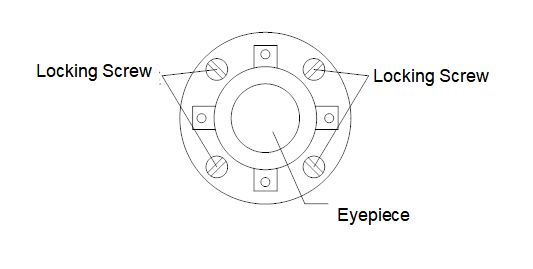
Firstly, remove the protective cover of the dividing plate seat located between the telescope eyepiece and the focusing handwheel, and you will see the four fixing screws of the dividing plate seat (see attached figure).
2. Use a screwdriver to evenly loosen the four fixed screws, rotate the dividing plate seat around the sight axis, and place point A 'on the position of the vertical wire.
Tighten the fixing screws evenly and use the above method to verify the calibration results.
4. Install the protective cover back in place.
15.4 Verticality between the sighting axis and the transverse axis (2C)
Inspection
Set target A at a distance of the same height as the instrument, accurately level the instrument, and turn on the power.
Aim the telescope at target A at the left position of the disk and read the horizontal angle
(Example: Horizontal angle L=10 ° 13 ′ 10 ″)
Release the vertical and horizontal brake handwheel to rotate the telescope, and turn the aiming plate to the right to aim at the same point
Before aiming at point A, tighten the horizontal and vertical brake handwheels and read the horizontal angle
(Example: Horizontal angle R=190 ° 13 ′ 40 ″)
4 2C=L - (R ± 180 °)=-30 ″ ≥ ± 20 ″, requires correction.
correcting
Adjust the horizontal angle reading to the correct reading after eliminating C using the horizontal micro adjustment handwheel:
R+C=190 ° 13 ′ 40 ″ -15 ″=190 ° 13 ′ 25 ″.
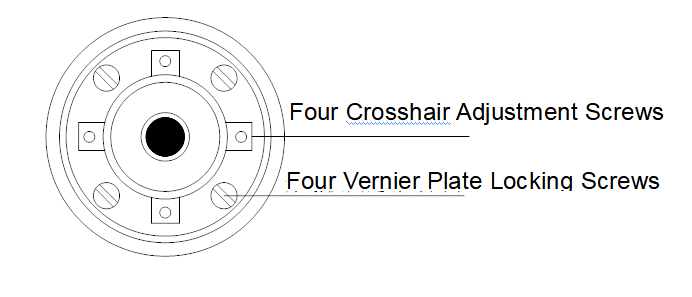
Remove the protective cover of the reticle holder located between the telescope eyepiece and the focusing handwheel, adjust the horizontal left and right crosshair correction screws on the reticle, loosen one side of the screw first and then tighten the other side, and move the reticle to align the crosshair center with target A.
Repeat the inspection steps until | 2C | < 20 ″ meets the requirements.
4. Install the protective cover back in place.
15.5 Vertical disk indicator zero point automatic compensation
Inspection
(1) After placing and leveling the instrument, align the direction of the telescope and the center of the instrument with the line connecting any foot spiral X, and tighten the horizontal brake handwheel.
(2) After turning on the device, the vertical dial indicator is reset to zero. Tighten the vertical brake handwheel, and the instrument displays the current vertical angle value pointed by the telescope.
(3) When the foot screw X is slowly rotated in one direction to a circumference distance of about 10mm, the displayed vertical angle changes accordingly and disappears, indicating that the instrument's vertical axis tilt has exceeded 4 ', which is beyond the design range of the vertical disc compensator. When the foot spiral is restored by reverse rotation, the instrument can repeatedly observe the changes in the vertical angle at the critical position, indicating that the vertical disc compensator is working normally.
correcting
When the instrument compensation fails or is abnormal, it should be sent to the factory for maintenance.
15.6 Vertical disk indicator difference (i angle) and vertical disk indicator zero point setting
Verify this project after completing the zero point error calibration of the tilt sensor and the calibration of the telescope reticle.
test
After placing and leveling the instrument, turn on the telescope and aim it at any clear target A, then read L on the left side of the vertical angle dial.
Rotate the telescope and aim at A again to read R on the right side of the vertical angle dial.
If the vertical zenith angle is 0 °, then i=(L+R-360 °)/2. If the vertical zenith angle is 0 °, then i=(L+R-180 °)/2 or (L+R-540 °)/2.
If | i | ≥ 10 ″, the zero point of the vertical disk indicator needs to be reset.
correcting:
◆ [Angle measurement]: Re measure the angle value
◆ [Setting]: Complete measurement
Accurately aim at any clear and stable target A at the same height as the instrument on the left side of the disk
Accurately aim at the same target A on the right side of the 2nd set
After completing measurements on both the left and right sides of the 3 disks, the indicator difference will be displayed
Repeat the inspection steps to re measure the index difference (i angle). If the indicator difference still does not meet the requirements, the three steps of calibration (indicator zero setting) should be checked for errors, whether the target alignment is accurate, etc., and then reset according to the requirements.
If it still does not meet the requirements after repeated operation, it should be sent to the factory for maintenance.
The vertical angle displayed during the zero point setting process is an uncompensated and uncorrected value, which is only for reference during the setting process and cannot be used for other purposes.
15.7 Laser point-to-point device
Inspection
Place the instrument on a tripod, draw a cross on a piece of white paper, and place it on the ground directly below the instrument.
Open the laser collimator and move the white paper to the center of the cross position spot.
Rotate the foot spiral to align the spot of the collimator with the cross point.
Rotate the sighting part by 90 degrees and observe the coincidence between the spot of the collimator and the cross point.
If the laser spot of the collimator always coincides with the cross point when the aiming part rotates, there is no need to calibrate. Otherwise, the following method should be used for calibration.
correcting
1. Remove the protective cover of the laser pointer.
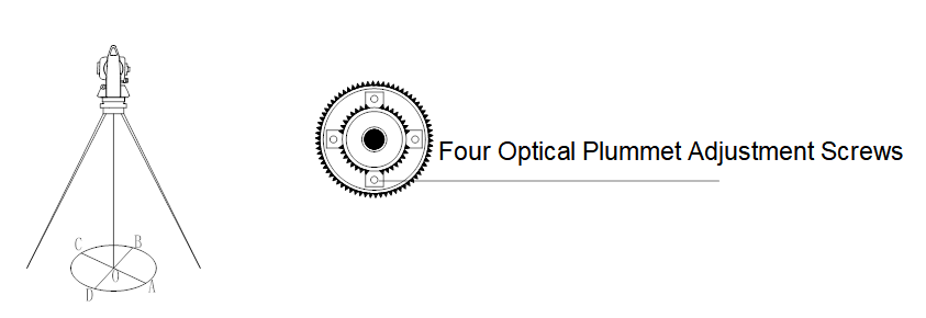
2. Fix the cross shaped white paper and mark the landing point of the spot sensor on the paper for every 90 °rotation of the instrument, as shown in the figure: points A, B, C, and D.
3. Connect the diagonal points AC and BD with a straight line, and the intersection point of the two lines is O.
4. Use an Allen wrench to adjust the four calibration screws of the aligner so that the center mark of the aligner coincides with the O point.
5. Repeat inspection step 4 to check and calibrate until it meets the requirements.
6. Install the protective cover back in place.
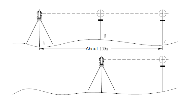
15.8 Instrument constant (K)
The instrument constant was checked at the factory and corrected internally to make K=0. The instrument constants rarely change, but we recommend conducting this test once or twice a year. This test is suitable for conducting on a standard baseline, or it can be performed using the following simple method.
test
Choose a flat site and place and level the instrument at point A. Use a vertical wire to carefully mark points B and C on the ground, spaced 50m apart on the same straight line, and accurately center the reflective prism or reflective plate.
After setting the temperature and pressure data, the instruments accurately measure the horizontal distance of AB and AC.
Place the instrument at point B and accurately align it to accurately measure the horizontal distance of BC.
The instrument ranging constant can be obtained:
K=AC-(AB+BC)
K should be close to zero. If | K |>5mm, it should be sent to the standard baseline field for strict inspection, and then corrected based on the inspection value.
◆ Prism plus constant: The instrument constant K measured in the presence of a prism
◆ Prism free constant: The instrument constant K measured without a prism
correcting
After strict inspection, it has been confirmed that the instrument constant K is not close to 0 and has changed. If the user needs to perform calibration, the instrument constant should be set according to the comprehensive constant K value
The vertical wire of the instrument should be used for orientation, strictly aligning points A, B, and C on the same straight line. The ground of point B should have a firm and clear alignment mark.
Whether the center of the prism at point B coincides with the center of the instrument is an important factor in ensuring detection accuracy. Therefore, it is best to use a tripod and a base that can be used interchangeably at point B. When using a three jaw prism connector and base interchangeably, the tripod and base should remain fixed and only the part above the prism and instrument base should be replaced to reduce non coincidence errors.
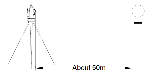
15.9 Coincidence between the sighting axis and the emitting electro-optical axis
test
-
Place a reflective prism 50 meters away from the instrument.
-
Use a telescope crosshair to accurately aim at the center of the reflecting prism.
3. Turn on the power and enter the distance measurement mode. Press the [Measure] button to measure the distance. Rotate the horizontal micro motion handwheel left and right, and the vertical micro motion handwheel up and down to perform electric sighting. Use the distance measurement light path to clear the left, right, and up and down intervals where the information flashes, and find the center of the distance measurement emission light axis.
4. Check whether the center of the crosshair of the telescope coincides with the center of the emitted electro-optical axis. If they are basically aligned, it can be considered qualified.
correcting
If the center of the crosshair of the telescope deviates significantly from the center of the emitting electro-optical axis, it must be sent to a professional repair department for calibration.
15.10 Base Foot Spiral
If the foot screw becomes loose, you can adjust the two correction screws used for adjusting the foot screw on the base and tighten the screws to the appropriate clamping force.
15.11 Reflector Prism Related Components
Reflective prism base connector
The long level and optical centering device on the base connector should be checked for correctness, and their calibration methods are described in sections 14.1 and 14.8.
2 pairs of vertical poles
As shown in Figure 14.8, mark a "+" at point C, and keep the lower tip of the centering rod upright at point C. Do not move the entire inspection, and support the two feet e and f on the cross line E and F respectively. Adjust the length of e and f to center the bubble of the centering rod circular level.
Place a leveling instrument at point A not far from the crosshair, use the crosshair center to aim at point C, fix the horizontal brake handwheel at the toe, tilt the telescope upwards to make the upper part of the centering rod D near the horizontal wire, and command the centering rod to only extend and retract the support foot e, so that D moves left and right to aim at the center of the crosshair. At this point, both points C and D should be on the centerline of the crosshair.
Place the instrument at point B on another cross line, using the same method. At this point, only extend and retract the support foot f to align point D of the centering rod with the centerline of the cross line at point C.
After calibration of the instrument at points AB, the centering rod has become vertical. If the bubble on the circular level on the rod deviates from the center at this time, adjust the three correction screws below the circular level to center the bubble as described in section 14.2.
Perform another calibration until the centering rod is perpendicular in both directions and the circular bubble is also centered.