Roads
-
Road File
-
Road Design
-
Data Lists
-
Calculation
-
3D View
8.1 Road File
8.1.1 New Road
Click Roads menu, click [New] button to open New Road dialog. Input the name of the new road and click [OK] to complete the road creation. The new road will be added to the list of roads in Work Space window. Since the parameters of the new road has not been entered yet, the road curve will not be displayed in the view interface.

Figure 8.1 New Road
8.1.2 Import Road
Click Roads menu, click [Import] button and select the road file in local path or connected device to import the road if you already have a road .trd file to be edited. After successful import, the imported road will be added to the list of roads in Work Space window and the road curve will be displayed in the view interface.
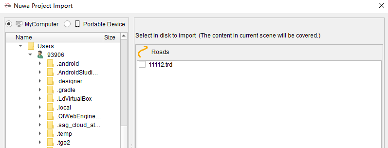
Figure 8.2 Import Road
8.1.3 Export Road
After finishing the edit and checking the parameters of the road, click [Export] button under Roads menu to export the edited road to the selected local path or connected device, then the road can be field staked in application such as Nuwa software.
8.2 Road Design
8.2.1 Alignment
After creating or importing the road, click [Alignment] button under Roads menu to edit the center line of road in the form.
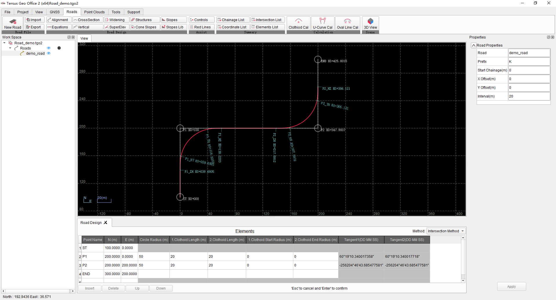
Figure 8.3 Alignment Parameters
Click the road in the Work Space window, input the start point, offset and other parameters of the road in the Properties window on the right.
Input the road center line parameters in the road design form according to Intersection Method or Elements Method. Then to road center line image will be drawn in the view interface according to the alignment parameters.
8.2.2 Equations
After creating and importing the road, click [Equations] button under Roads menu to edit the parameters of the equations of the road in the form.
8.2.3 Cross Section
Click [Cross Section] button to edit the cross sections parameters of road in the form.
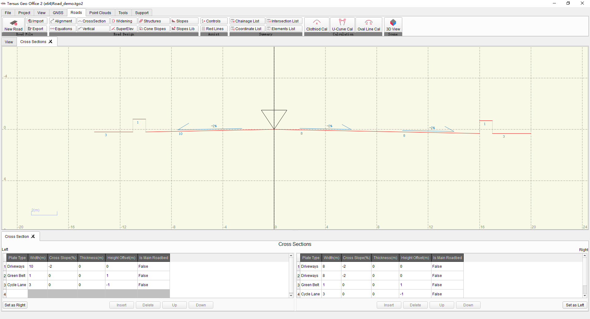
Figure 8.4 Cross Section
Input parameters of plates, the cross section graphic will be drawn in cross sections view.
8.2.4 Vertical
Click [Vertical] button to edit the vertical profile parameters of road in the form.
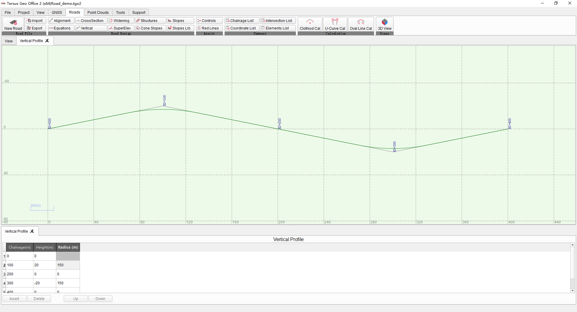
Figure 8.5 Vertical Profile
Input parameters of vertical profile, the graphic will be drawn in vertical profile view.
8.2.5 Widening & Super Elevation
Click [Widening] and [Super Elev] buttons to edit the parameters of the width and elevation changes of the cross sections at different mileages in the forms.

Figure 8.6 Widening
Enter the change parameters relative to standard cross section in the form, then drag the mileage progress bar on the right side of form to show cross sections change in the view.
8.2.6 Structures
Click [Structures] button to enter the structure parameters and preview it in the form.
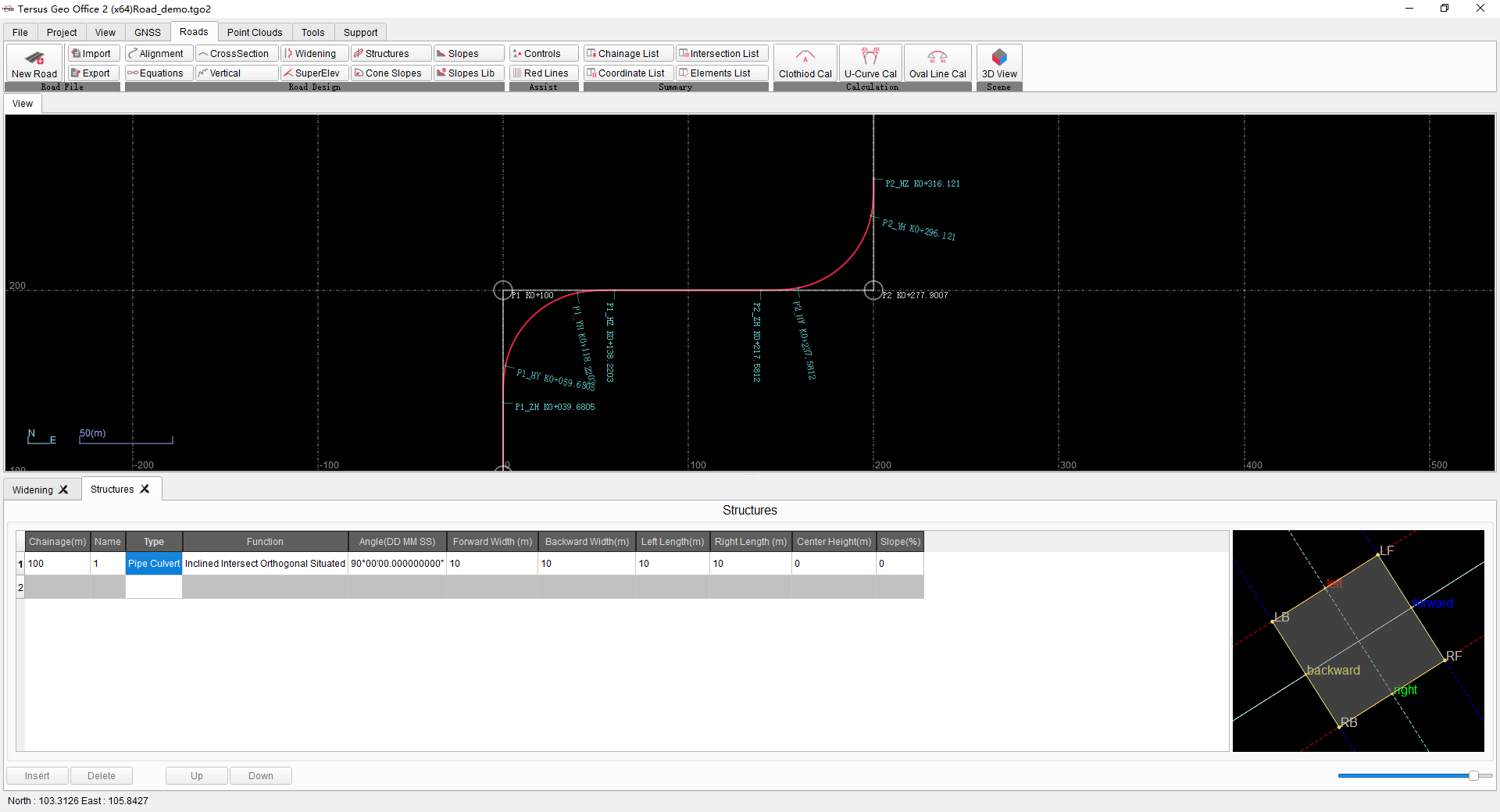
Figure 8.7 Structure
8.2.7 Cone Slopes
Click [Cone Slopes] button to edit parameters of cone slope in the form and preview it.
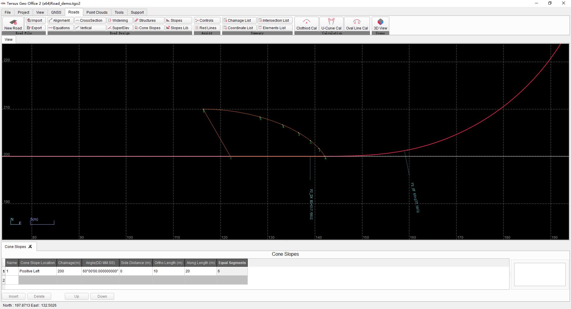
Figure 8.8 Cone Slopes
8.2.8 Slopes & Slopes Lib
Click [Slopes Lib] button to edit slopes library in form.
Click [Slopes] button to edit slope parameters and select using template from Slopes Lib, and then preview in slopes view.
8.2.9 Controls & Red Lines
Click [Control Points] button to edit the road control points in the form.
Click [Red Lines] button to edit the red line of land acquisition on the left and right sides of road in the form.
8.3 Data Lists
After editing roads parameters, click [Chainage List] button under Roads menu to display Chainage and Coordinate List, where shows coordinates and parameters of center line at different mileages according to interval set in properties window.
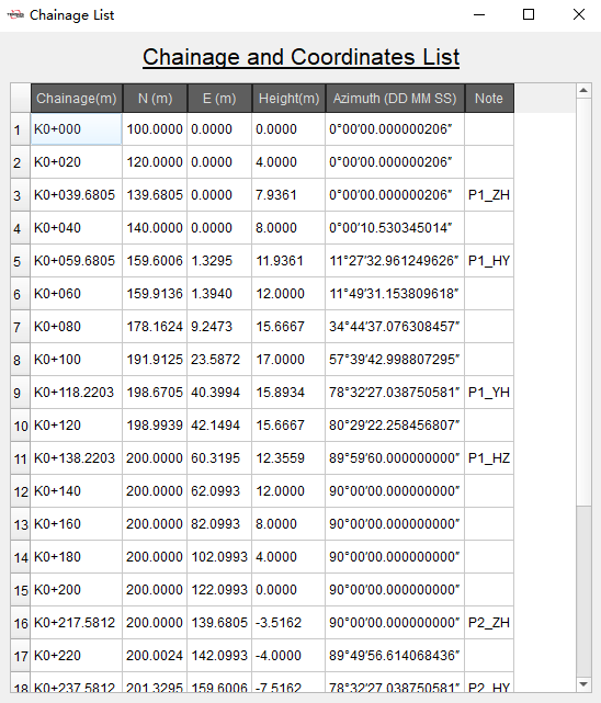
Figure 8.9 Chainage List
Click [Coordinate List] button under Roads menu to display Coordinates of Points on Center-line and Side-line List, where shows coordinates and parameters of points on cross sections at different mileage.
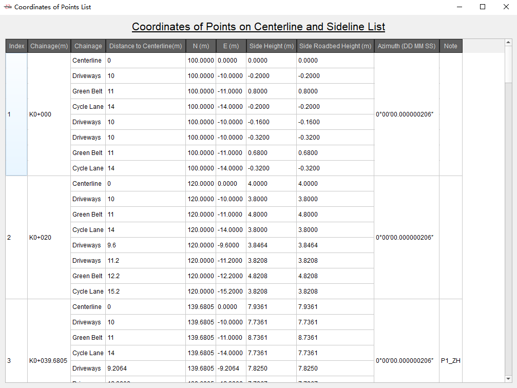
Figure 8.10 Coordinate List
Click [Intersection List] button under Roads menu to display Intersection Points and Parameter List, where shows intersection parameters of road alignment.
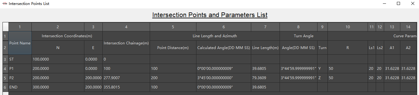
Figure 8.11 Intersection List
Click [Elements List] button under Roads menu to display Elements List, where shows elements and parameters of road alignment.
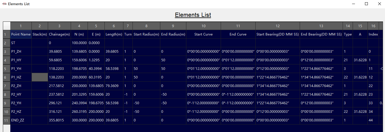
Figure 8.12 Elements List
8.4 Calculation
Click [Clothoid Cal] button under Roads menu to open Clothoid Calculation tool, where to calculate parameters of clothoid.

Figure 8.13 Clothoid Cal
Click [U-Curve Cal] button to open U-Curve Calculation tool, where to decompose virtual intersection of u-curve into two intersections for normal input in intersection method.
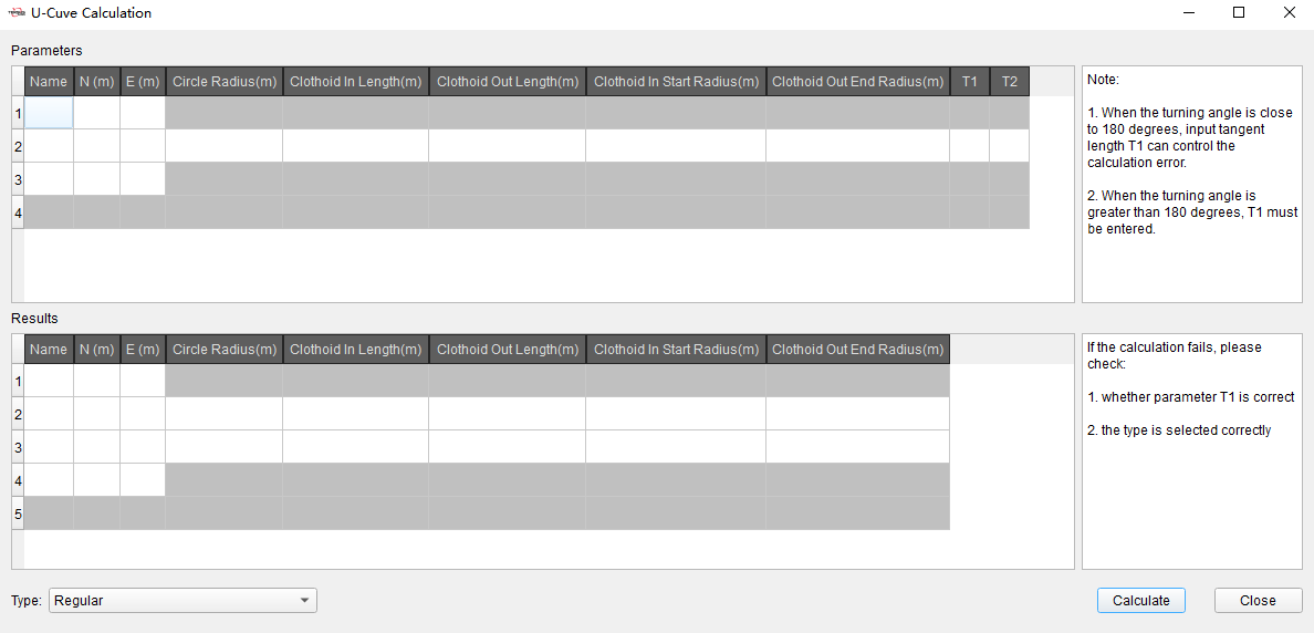
Figure 8.14 U-Curve Cal
Click [Oval Cal] button to open Oval Calculation tool, where to decompose intersection of oval curve into two intersections for normal input in intersection method.
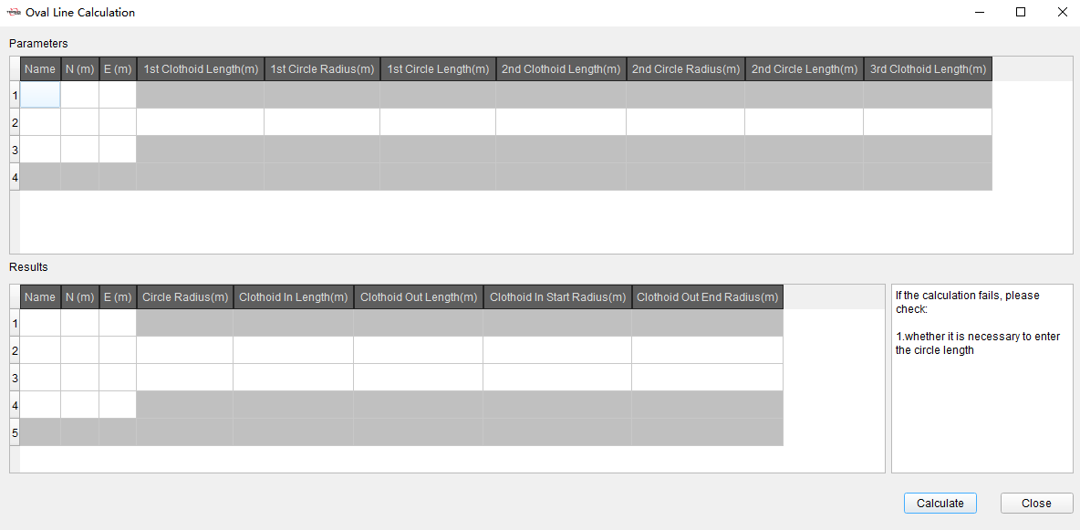
Figure 8.15 Oval Cal
8.5 3D View
After editing road parameters, click [3D View] button under Roads menu, open 3D view display. In 3D view interface, use the mouse wheel to zoom the display. Use the left mouse button to rotate the display and the right mouse button to drag the display, to adjust the 3D display angle of road.
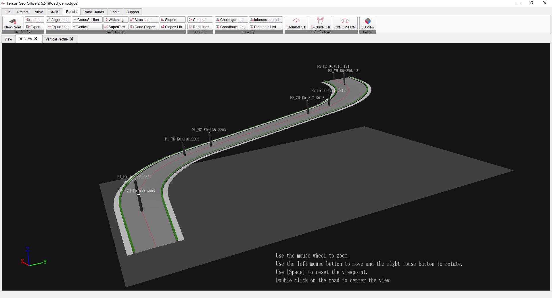
Figure 8.16 3D View