Quick Start
-
New Project
-
Edit Coordinate System
-
GNSS Post Processing
-
Road Data Editing
-
Point Clouds Data Processing
2.1 New Project
Click File menu, click [New] button, enter the project name or use current time as the default name, select the directory, click [OK] to create a new project.
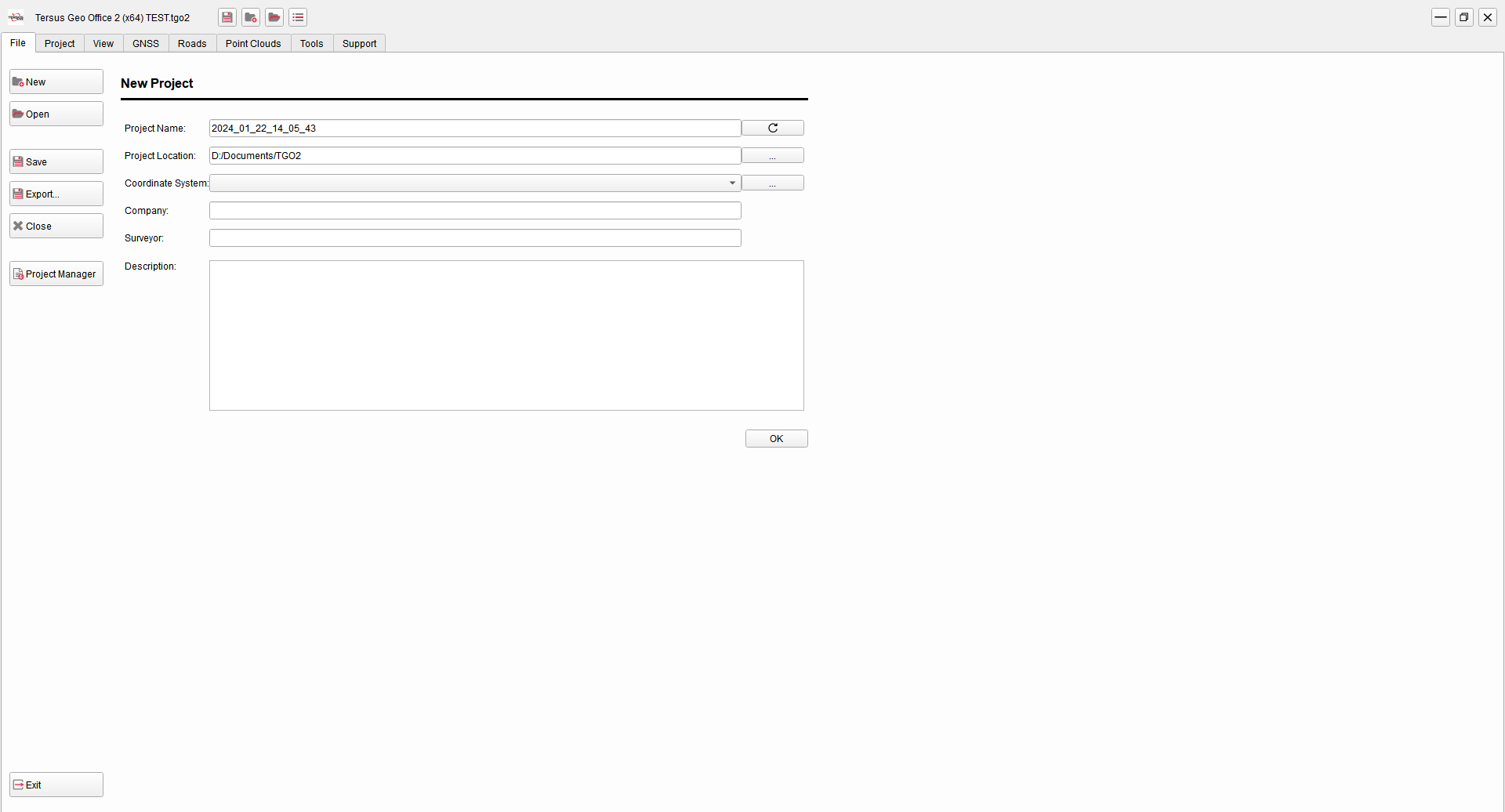
Figure 2.1 Quick Start - Create New Project
When creating new projects, select none coordinate system, or select from drop-down list. If there is no coordinate system that meets the requirement in the list, click [...] to open the coordinate system manager. Select the coordinate system in the predefined list or customized list, click [Add] to add it to the selectable coordinate system list on the left.
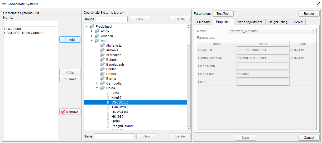
Figure 2.2 Quick Start - Coordinate System Manager
2.2 Edit Coordinate System
Click Project Menu after opening a project, click [Coordinates] to check or edit the coordinate system parameters of the current project. Edit the local ellipsoid and datum conversion parameters in Ellipsoid. Edit the projection and parameters such as central meridian, false north, false east in Projection. Select geoid model file in Geoid.
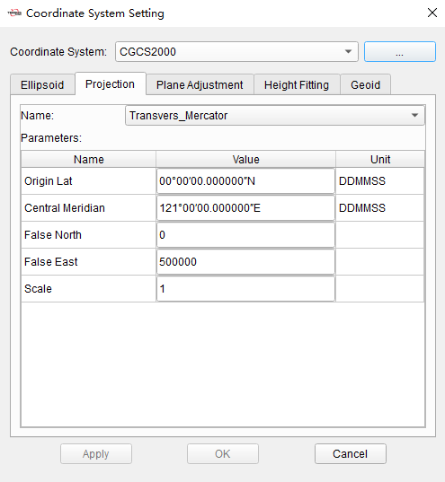
Figure 2.3 Quick Start - Edit Coordinate System
Switching the coordinate system by selecting it directly from the drop-down list is also allowed. If there is no coordinate system that meets the requirement in the list, click [...] to open the coordinate system manager. Select the coordinate system in the predefined list or customized list, click [Add] to add it to the selectable coordinate system list on the left.
2.3 GNSS Post Processing
Click GNSS Menu, click [Import] and select GNSS files in RINEX format or TRS format to import. The workspace on the left will show the imported data, containing stations, baselines and loops. The view interface will show the location of stations and baselines.
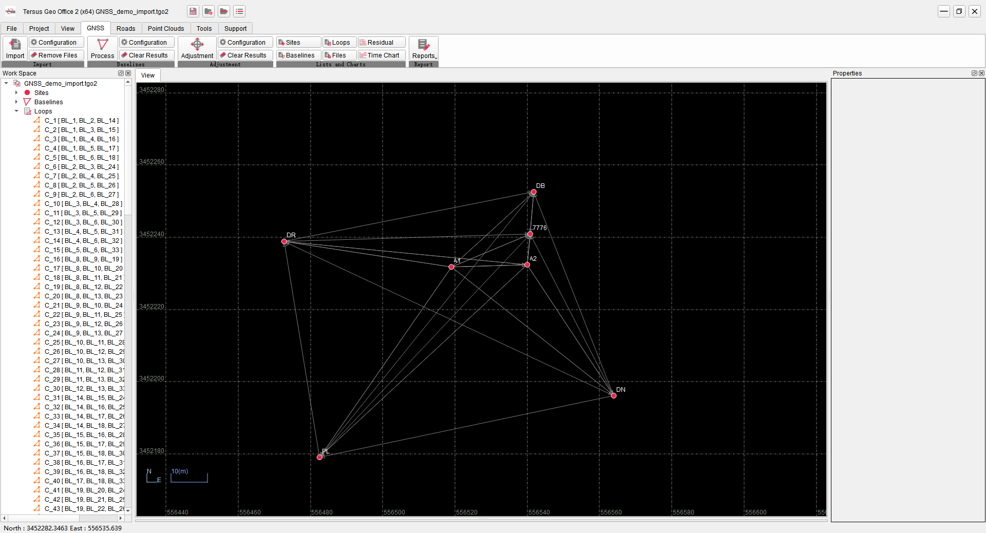
Figure 2.4 Quick Start - GNSS Data Import
Click [Files] under the GNSS TAB to display the information of files in a list. Click an file, and confirm or edit the station name, receiver information and antenna information of the corresponding station if the properties window on the right.
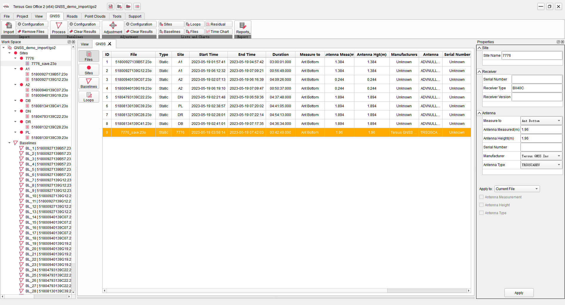
Figure 2.5 Quick Start - GNSS Data Edit
Click [Process] under the GNSS TAB to perform baseline processing. Baselines in the view will be highlighted, indicating the baselines have been processed. Click [Baselines] under GNSS TAB to display the detailed information of the baselines in a list.
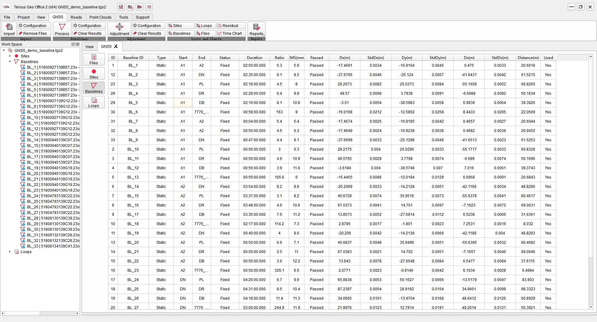
Figure 2.6 Quick Start - GNSS Baselines
If the baseline can not get a fixed solution, or the RMS value in the baseline processing result is large, select the baseline and right click on [Residual Plot]. Click the satellite or click [Previous] and [Next] to display the residuals of each satellite. According to the residuals, set the satellite unused, or draw a box to delete part of the observation data of the satellite and re-process it to get a more accurate result.
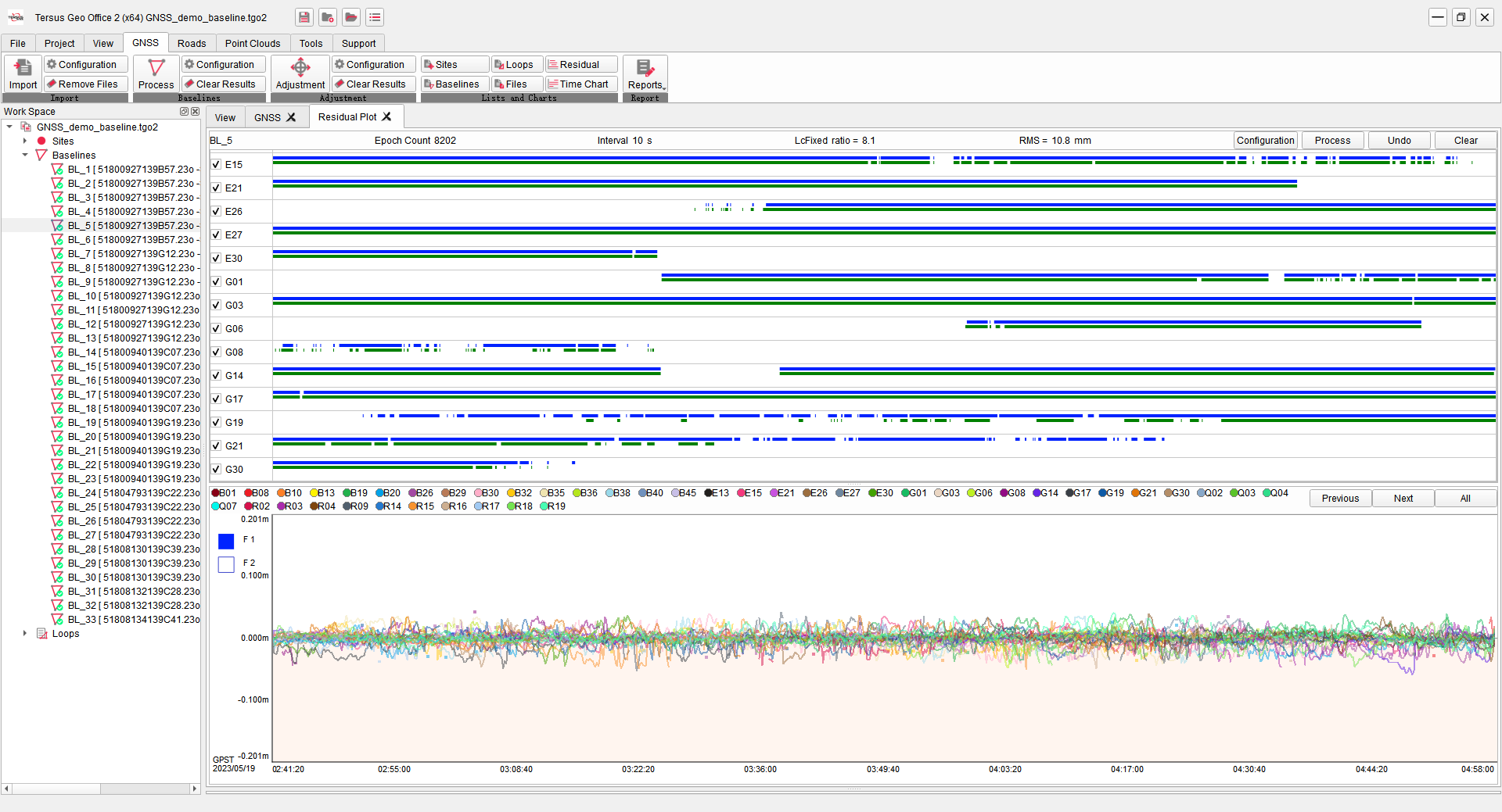
Figure 2.7 Quick Start - GNSS Baseline Residual Processing
After the baselines processing is completed, start network adjustment next. If there are control points, click [Sites] and select control points in the list, click [Constraint] in the right properties window, select WGS84 Constraint or Local Constraint and enter the constraints coordinates, then the known points in the sites list will be labeled.
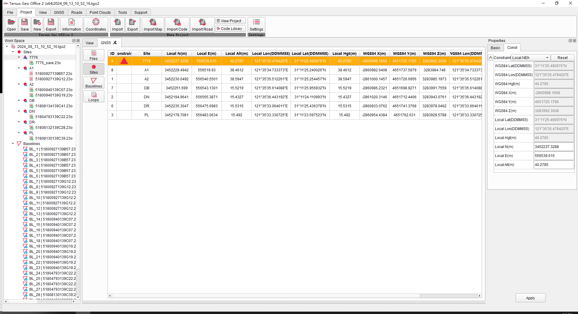
Figure 2.8 Quick Start - GNSS Constraints
Click [Adjustment] under the GNSS TAB, select [Auto] to perform adjustment according to the constraints. Click [Report] to open and view the report in browser, or click [Reports] under GNSS TAB and select other reports from the drop-down menu to open.
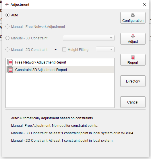
Figure 2.9 Quick Start - GNSS Network Adjustment
2.4 Nuwa Project Editing
Click [Import] to select data in Tersus Nuwa field application from local paths or connected controller device. Choose the projects, vector maps, roads or code sets to import.
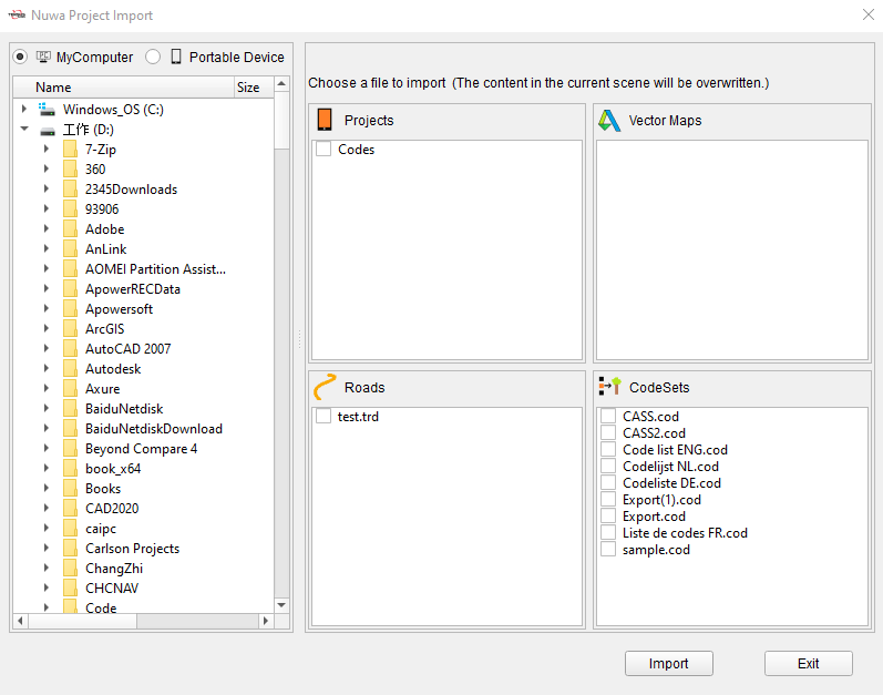
Figure 2.10 Quick Start - Nuwa Project Import
Click [View Project] to show the points and lines in the Nuwa project. Edit Code, Attributes or antenna heights for points if needed.
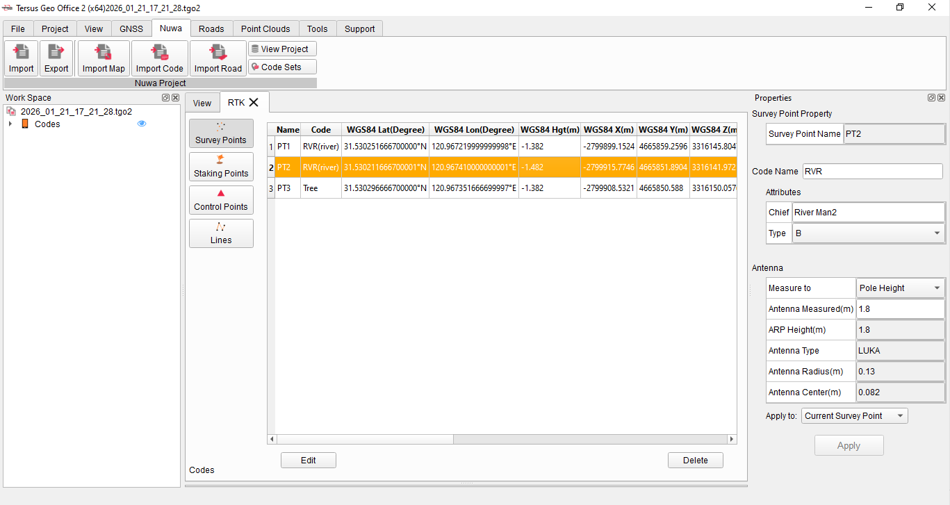
Figure 2.11 Quick Start - Nuwa Project Editing
After modification, click [Export] to export modified project to local paths or a connected controller device. If the controller device is selected, the modified project will be automatically saved to the TersusSurvey folder and can be directly opened after restarting the Nuwa application on the controller.
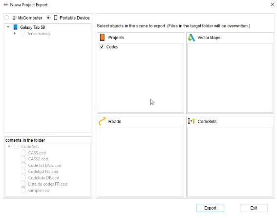
Figure 2.12 Quick Start - Nuwa Project Export
2.5 Road Data Editing
Click [New Road] under the Roads TAB and enter a road name to create a new road, or click [Import] and select a local road file in .trd format to import.

Figure 2.13 Quick Start - New Road
Click [Alignment] under the Roads TAB, input the starting point parameters of the road in properties window on the right side, and input the center line parameters in the road design window at the bottom in Intersection Method or Elements Method. After inputting, the graph of the alignments corresponding to the inputted parameters will be displayed in the view window.

Figure 2.14 Quick Start - Road Alignments Parameters Editing
Click [Equations], [Vertical], [Cross Section] and other buttons under the Roads TAB to input the parameters of the road and display the corresponding graphics.
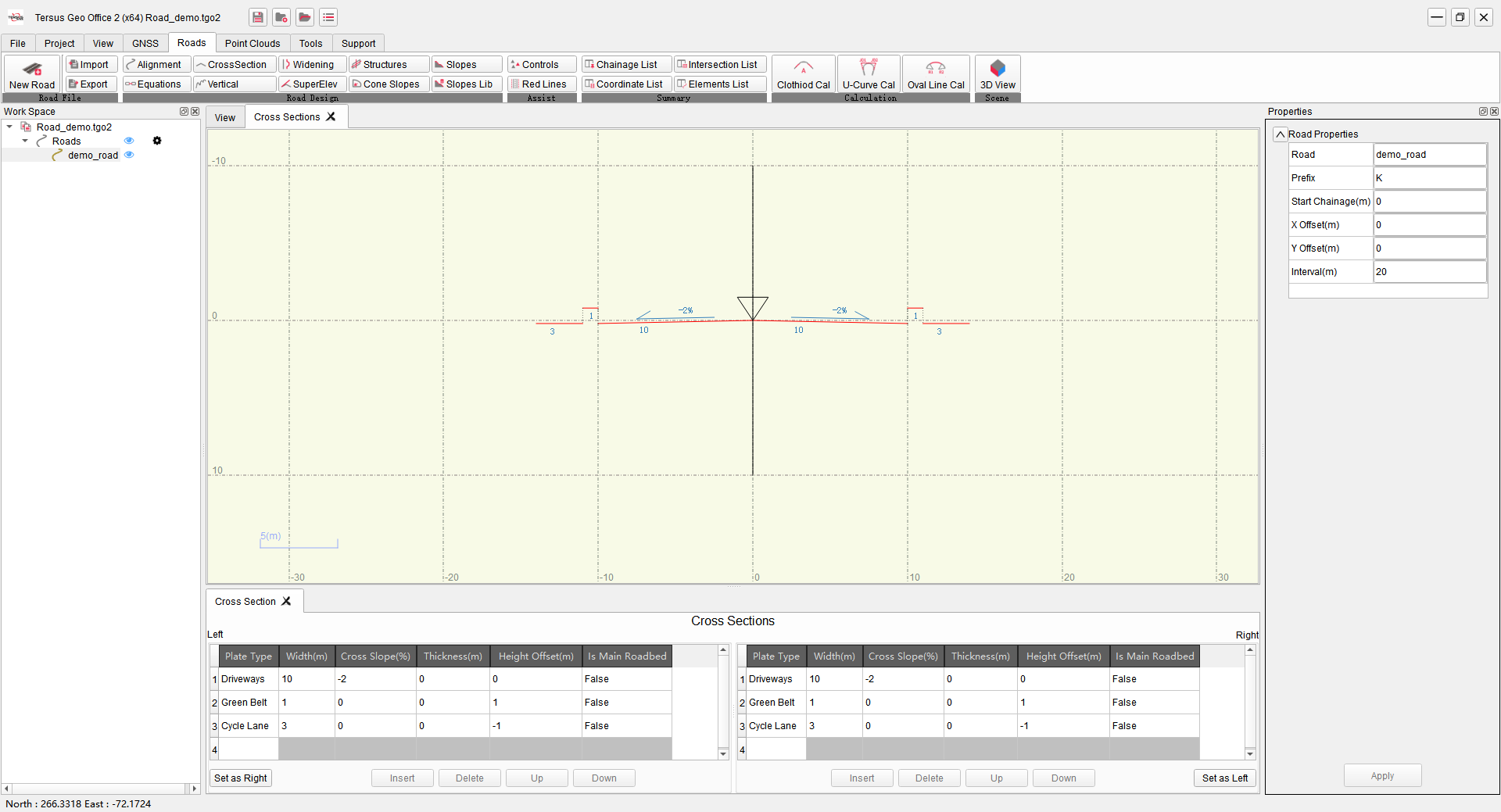
Figure 2.15 Quick Start - Road Cross Sections Parameters Editing
Click [Coordinate List] to check the edited road coordinates. Click [3D View] to view the edited road graphics. Then click [Export] to export edited road in .trd format and send it to Tersus Nuwa App to stake the road on field.
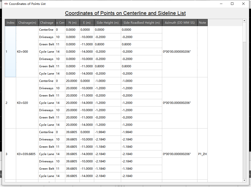
Figure 2.16 Quick Start - Road Coordinates
2.6 Point Clouds Data Processing
Click [Show] to open the point clouds window. Click [LAS Files] and click on the Las source files [+] to select one or more .las files to import.

Figure 2.17 Quick Start - Point Clouds LAS Files Import
Click on the Datasets [New] and check the attributes column of the LAS files, enter the name and wait for the data import of the checked attributes to complete.
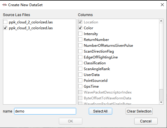
Figure 2.18 Quick Start - Point Clouds Datasets Import
After successful import, the view interface shows the point clouds graph. Use the mouse wheel to zoom, the left mouse button to adjust the view angle, and the right mouse button to move.
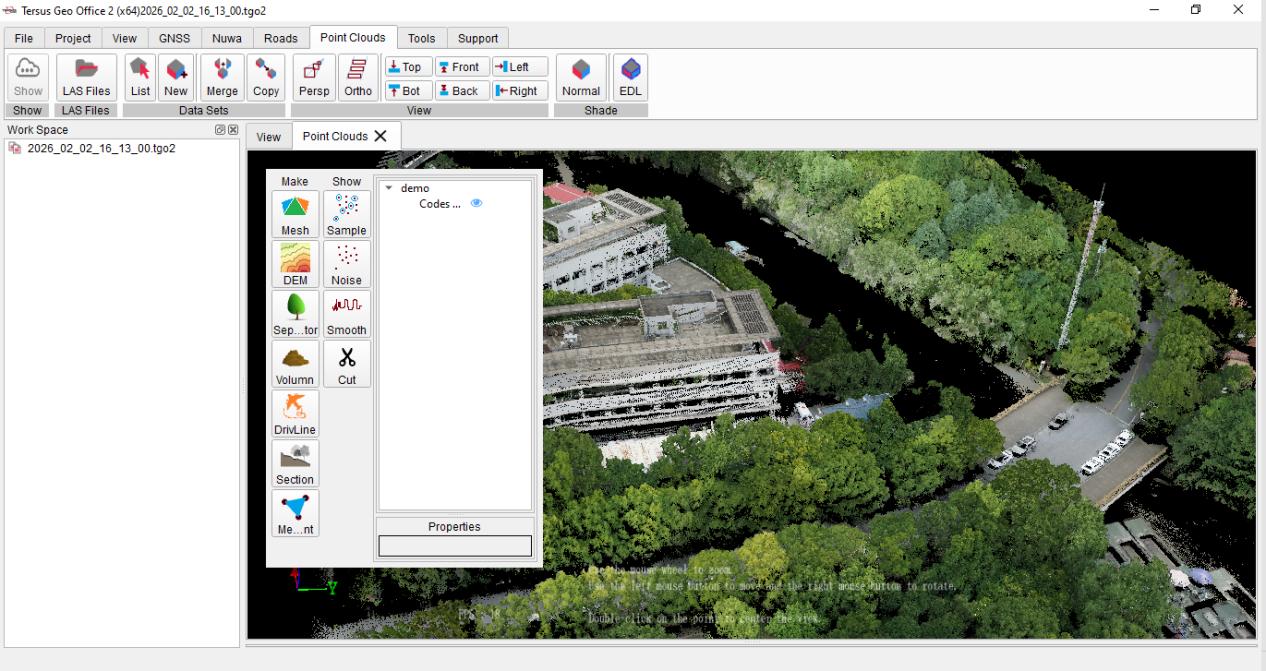
Figure 2.19 Quick Start - Point Clouds Display
Select the items to perform Mesh, Sample, Cut, Volume calculation or other operations.
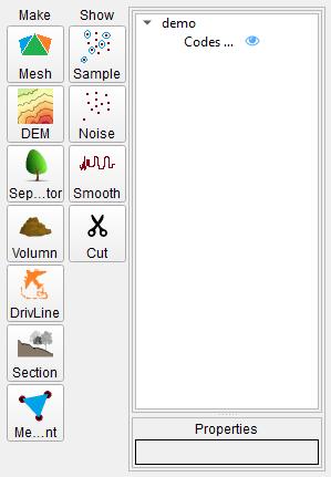
Figure 2.20 Quick Start - Point Clouds Data Editing