Quick Start Guide
3 Operating Procedure
Note: The following points should be noted when using and storing the device:
- Do not operate the device's connections while powered on, as it may damage the device.
- The device's operating temperature range is from -20°C to +60°C. It should be used within the specified environmental temperature range.
- Avoid placing the device in humid or corrosive environments frequently.
- The device is not waterproof. Do not operate it in rainy or snowy weather.
- During operation, keep an eye on obstacles in front of you to avoid collisions with the device.
- When placing the device, ensure it is on a level surface and monitored to prevent it from tipping over.
3.1 Before Scanning
3.1.1 Power on the device
- Turn on the device by pressing the SENSOR button first, followed by the MASTER button
- Wait for 30 seconds, then turn on the camera power.
3.1.2 Connect to the control system
Note: During use, do not exceed a distance of five meters from the device to ensure a good WiFi connection signal. Connect to the WIFI of device Open the phone browser and enter the address: 192.168.95.110:8888. Wait for a moment to access the data collection interface.
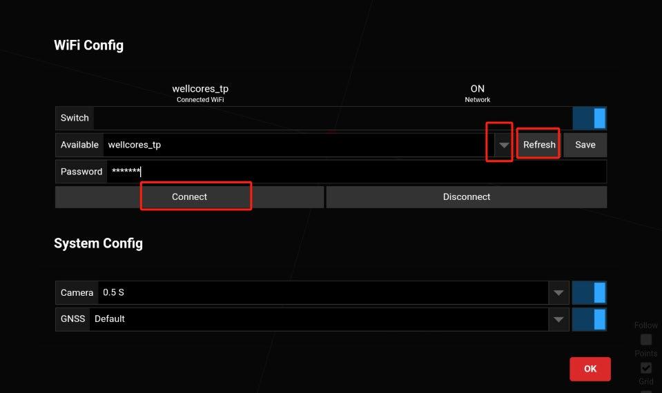
3.1.3 Connect the device to an available network
If RTK mode is required, there are two ways to connect the device to the network: ① Insert a wireless USB network card.
② Click "Config", then click "Refresh" to refresh the WiFi list. Click the triangle icon to select a WiFi network, enter the password, and click "Connect" to connect the device to an available WiFi network. (It is recommended that the WiFi name be in English.)
Figure 3-1
3.2 Data Collecting
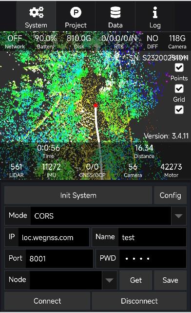
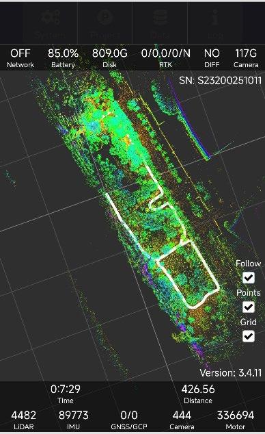
3.2.1.1 TersusMVP Capture
The TersusMVP Capture Web UI includes the following five functional zones: System:configure the device and connect to CORS to receive differential information. Project:set project name, start/stop collecting, grab GCP, show real time pointcloud. Data:View the collected projects. Log:Record and display the device’s operation log information. Status:sensor status, RTK status, image taken. The sensor status and project information are as follows: Network: ON-the device has connected to an available network;OFF-Network connection interrupted. Battery: remaining battery level. Disk: remaining disk capacity. RTK:RTK status /HDOP/satellite number/positioning status, when the RTK status is 4, and HDOP<3.0, the positioning status will be Y (Yes), indicating that the device is fixed, or the
positioning status will remain as N (NO). DIFF:"YES" indicates that the RTK differential signal is being received normally; "NO" indicates that the RTK differential signal has not been received. Time: collecting time. Distance: distance from the starting position. LiDAR: LiDAR data volume. IMU: IMU data volume. GNSS: GNSS data volume. GCP: GCP count. Camera: image count.
Figure 3-2
3.2.1.2 Backpack Operating Procedure
-
Place the device in an open area with the LiDAR sensor facing a fixed, stationary structure. Make sure no fast-moving objects pass in front of the LiDAR.
-
Click the MASTER and SENSOR button, and then turn on the camera. Connect your phone to the device’s Wi-Fi, open a browser, and enter the IP address 192.168.95.110:8888 to access the control interface.
-
Click "Config" to select whether to enable the panoramic camera and RTK mode. If RTK is used, you need to configure the device to connect to an available Wi-Fi network (see 3.1.3) and then connect to CORS (see 3.2.1.2 5.).
-
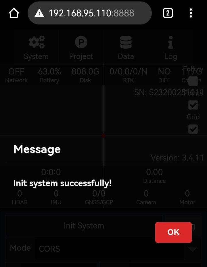
Click the "Initialize" button to start the system self-check. If the self-check is successful, a "Init system successfully" dialog box will pop up. Click "OK" to proceed.
Figure 3-3
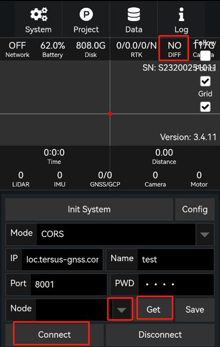
- Enter the CORS server IP address, port, username, and password. Click “Get,” then click the downward arrow select an available mount point. After that, click “Connect.” Once connected successfully, the differential data status “DIFF” will change from “NO” to “YES”.
Figure 3-4
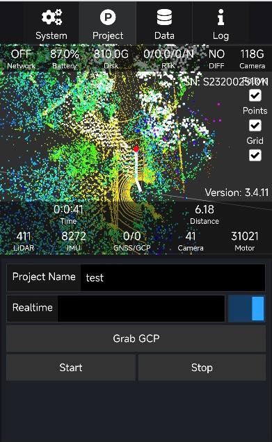
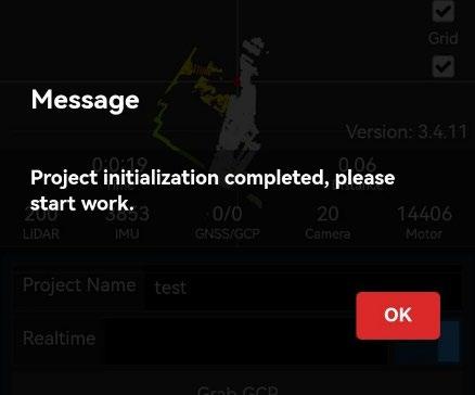
- Move to an open area and wait until the positioning status shows 4 (Fixed) and the HDOP value is less than 3.0 before starting the data collection. Click "Project," enter the "Project Name". To view the point cloud in real time, you need to turn on the “Realtime” switch. Then click "Start". After approximately 14 seconds, a dialog box will appear indicating the beginning of the operation, and data collection will commence.
Figure 3-5
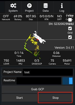
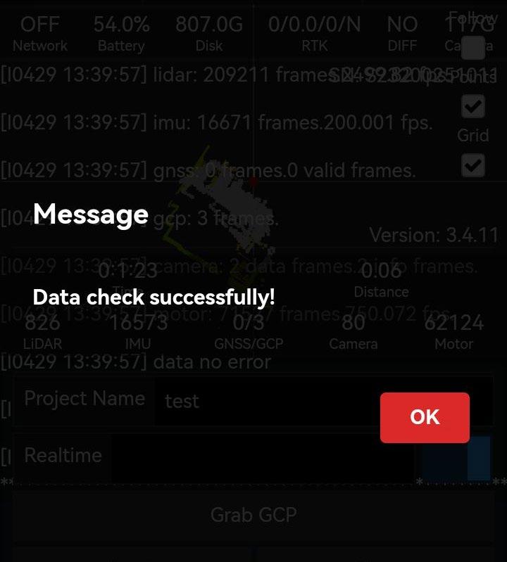
- When data collection is complete, click the “Stop” button (you must stop the collection when the battery level is close to 0%). A “Data check successfully” dialog will appear—click “OK” to confirm.
Figure 3-6
3.2.1.3 Handheld Operating Procedure
1.Screw the Target Board onto the bottom of the Handhel Module and secure it tightly with screws. Place the LiDAR horizontally on the base in an open area, facing a stationary structure. Make sure no rapidly moving objects pass above the LiDAR. 2.Attach the shoulder strap to the Master Module, and connect the data cable between the Master Module and the Handheld Module.
3.Click the MASTER and SENSOR button, and then turn on the camera. The remaining operations are the same as those for backpack operation.
3.2.1.4 Grab GCP
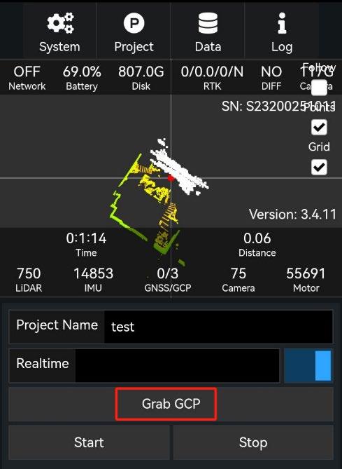
1.Align the cross-shaped hole on the Target Board with the ground control point (GCP). As long as the Target Board is firmly positioned on the GCP, the LiDAR module’s orientation— whether vertical or tilted—will not affect the final result. Then, tap the “Grab GCP” button on the mobile interface.
Figure 3-7
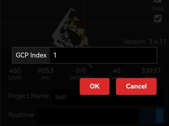
2.A dialog box will pop up to record the GCP number. Click “OK”. The GCP name cannot and should not be changed.
Figure 3-8
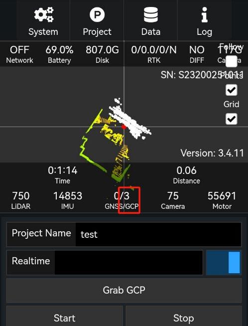
3.When you see the number of GCPs increase, it indicates that the current collection is complete.
Note: The number of GCP must not be less than four, and their positions must not lie on a straight line. They should be evenly distributed across the survey area.
Figure 3-9
3.3 Data Copying and Power Off
3.3.1 Data Copying
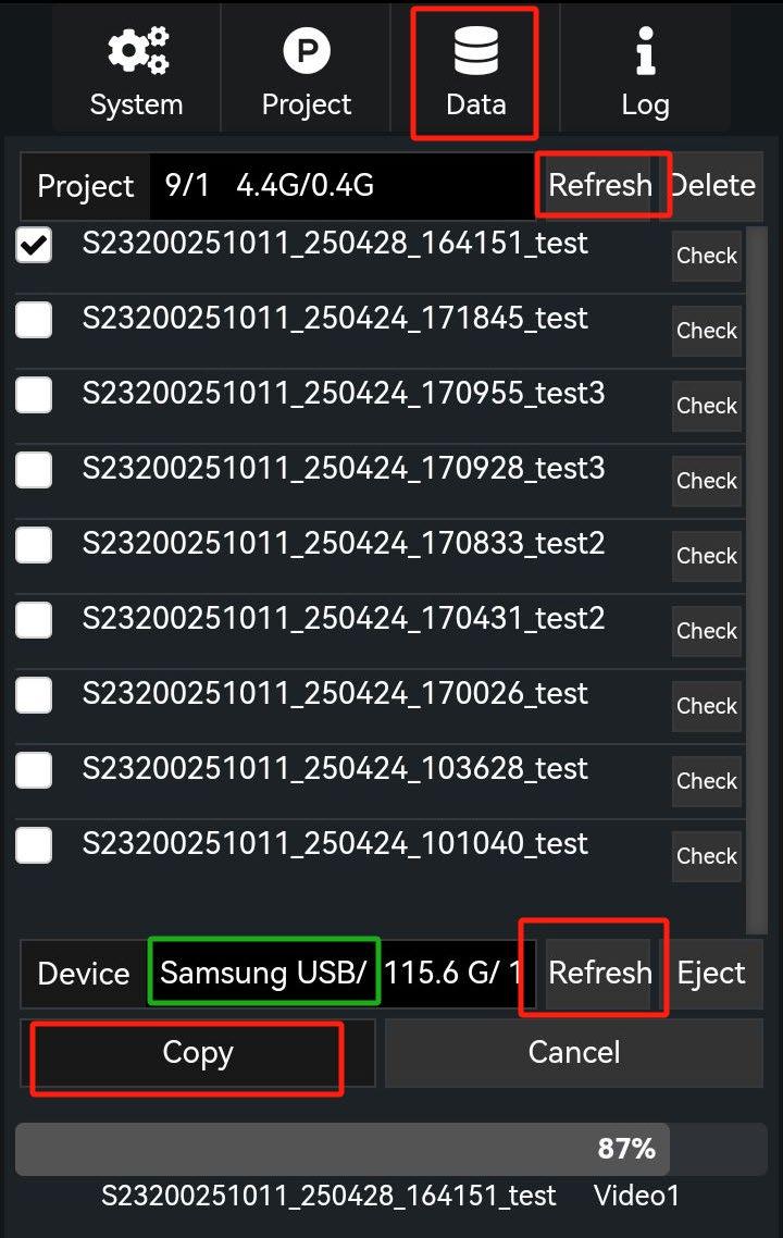
The USB drive used for data copying must be formatted as an NTFS file system. A USB 3.0 drive is recommended. Insert the USB drive into the inner USB 3.0 port on the main unit panel (the port near the back frame in backpack mode).
Use the software to copy the data:
- Click the "Data" menu tab and select "Refresh" to display project files from completed tasks.
- Select the data file to be copied.
- Click "Refresh" in the device panel to check the remaining storage space on the USB drive and compare it with the size of the data file.
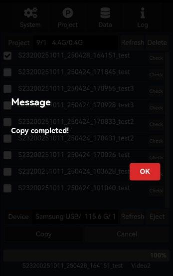
- Click "Copy." When the transfer is complete, a "Copy completed" dialog box will pop up.
Figure 3-10
3.3.2 Power Off
Shut down the device in the following steps:
- Press and hold the camera power button to turn off the camera.
- Press the MASTER power button; the master power indicator (red) should turn off.
- Press the SENSOR power button; the sensor indicator (blue) should turn off.

Figures
Support: support@tersus-gnss.com