Hardware Overview
1 Components
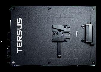
1.1 Master Module
For data storing, information sending and receiving.
Figure 1-1
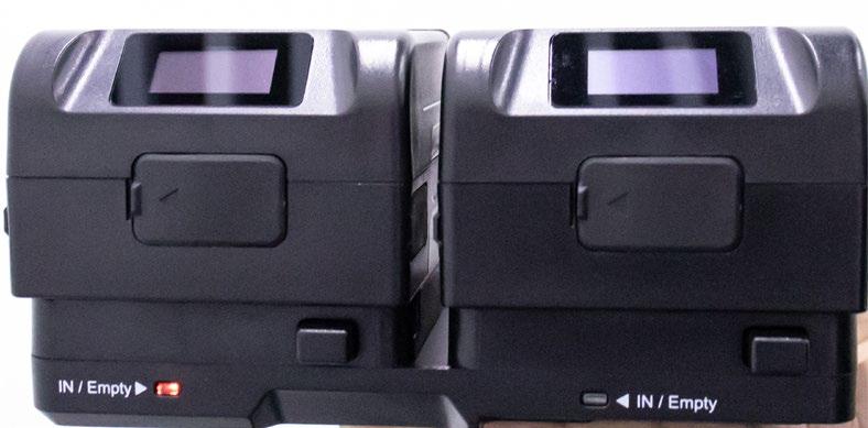
1.2 Handheld Module
For LiDAR data and image collecting. Figure 1-2 Handheld Module, without camera (left), with camera (right).
1.3 Li-ion Battery
For power supply.
Figure 1-3
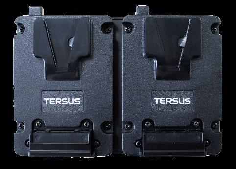
1.4 Hot-swappable Hanging Board
Replacing the battery without interruption.
Figure 1-4
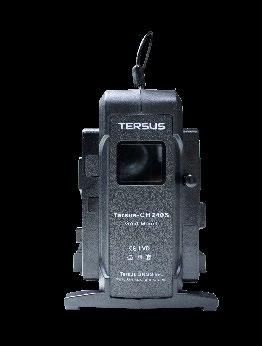
1.5 Charger
For battery charging.
Figure 1-5
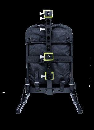
1.6 Backpack Bracket
For carrying operation methods.
Figure 1-6
1.7 RTK Module
For receiving satellite signal and base station data (RTK)
Figure 1-7
1.8 Dongle
For TersusMVP Mapper data processing.
Figure 1-8
1.9 USB Driver
For data copy.
Figure 1-9
1.10 Controller For device control through web UI.
Figure 1-10
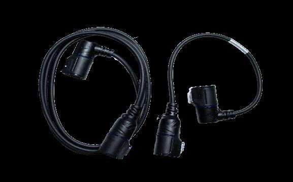
1.11 Cable For power supply and data transmission between modules.
Figure 1-11
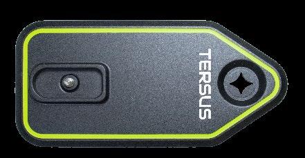
1.12 Target Board For GCP grabbing.
Figure 1-12
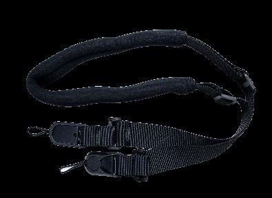
1.13 Shoulder Strap For Master Module carrying in Handheld method.
Figure 1-13
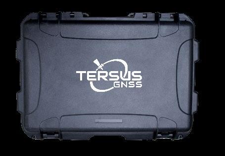
1.14 Carrying Case For device transportation and storage.
Figure 1-14
2 Installation and Dismantling
2.1 Installation
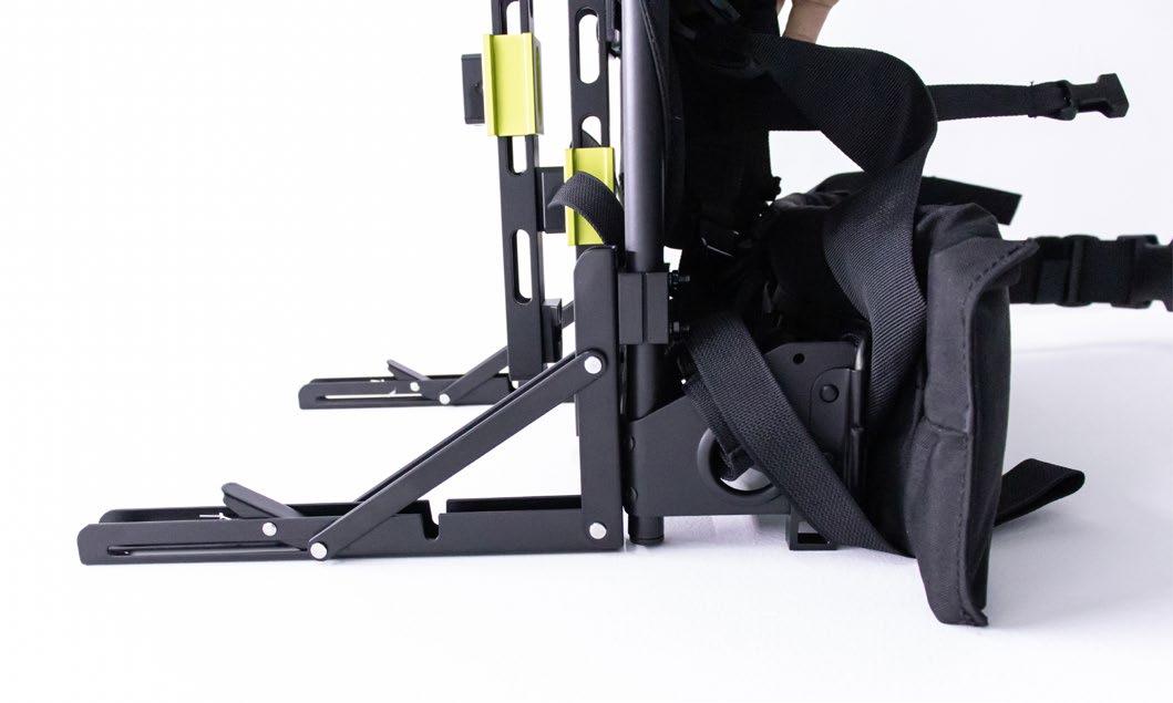
- Deploy the triangular support rod under the backpack bracket to ensure stable placement on planar surfaces.
Figure 2-1
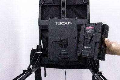
- Mount the battery onto the hot-swappable hanging board. If the red indicator light is illuminated, it indicates proper installation. Then integrate the complete with the Master Module.
Figure 2-2
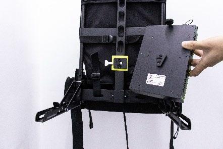
- Mount the complete of the battery and Master Module with the Backpack Bracket.
Figure 2-3
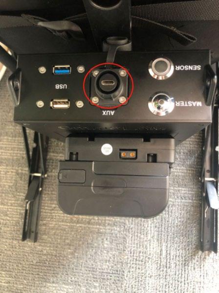
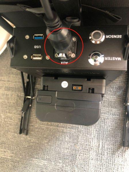
- Align the master cable with the Type-C port on the Master Module, and gently insert the cable until the latch on the Type-C cable clicks and pops up, indicating that the master cable has been properly connected.
Figure 2-4
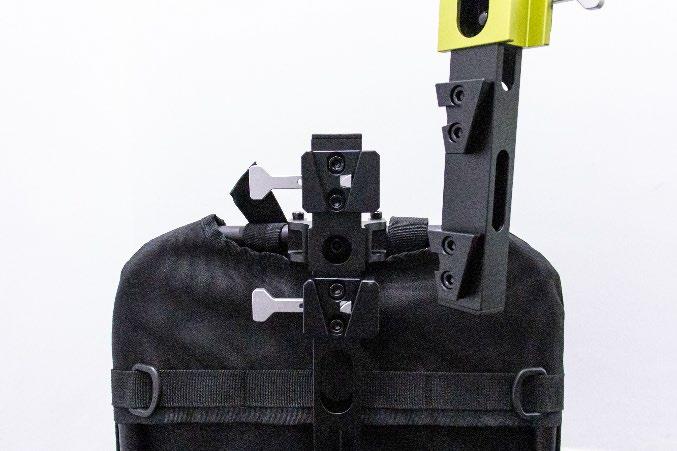
- Press the female buckle of the latch with your palm, and push the male buckle on the mounting rod downward into the female buckle. Once the mounting rod is in the correct position, the latch will lock securely. You can run your fingers over the latch joint—if it feels flat and smooth without any bumps, and the mounting rod does not move when gently shaken, it means the latch is properly locked.
Figure 2-5
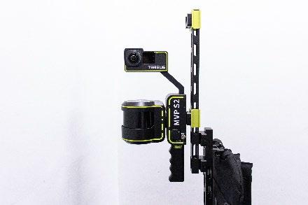
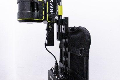
- With one hand pressing the female buckle of the latch and the other supporting the LiDAR sensor, push the male buckle on the LiDAR into the female buckle to mount the sensor onto the upper part of the backpack brecket. After installation, run your fingers over the quick- release latch joint—if it feels flat and smooth without any bumps, and the LiDAR remains
stable when gently shaken, it means the latch is properly locked. Then, insert the master cable into the Type-C port on the LiDAR sensor. Gently push it in until the latch on the Type- C cable clicks and pops up, indicating that the main cable has been properly connected.
Figure 2-6
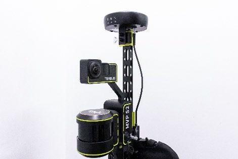
- Mount the RTK module on the top and connect the cable. Align the red dot on the RTK cable with the red dot on the main unit’s port, and gently insert the cable. Make sure to hold the cable by the metal ring, not by the black part of the cable. (All cables with red dots must be connected in this manner.)
Figure 2-7
- Double-check that all components are properly installed, the latches are securely fastened, and there is no looseness when gently shaking by hand.
Figure 2-8
2.2 Dismantling
Note: If the device will not be used for an extended period, please disassemble it and store it in the provided transport case to prevent accidental damage from impacts or scratches. First, turn off the switch on the camera. After the camera's indicator light has completely gone out, then turn off the switch on the main unit. Disconnect all the cables and place them in their designated spots in the transport case. Then, remove the antenna disc, LiDAR module, RTK Module, Master Module, and battery in order from top to bottom, and place them properly inside the transport case. Remove the mounting rod and install it at the lower part of the back frame, then restore the triangular rod.


Figures


Support: support@tersus-gnss.com