Tersus MVP S1 Mapper Processing Software
Tersus MVP S1 Mapper is a PC processing software for Tersus GNSS handheld 3D LiDAR scanners. It provides raw data parsing, 3D point cloud visualization, and measurement analysis. When paired with Tersus GNSS handheld LiDAR products, it supports the complete workflow from data acquisition to analysis, enabling full application of 3D point clouds.
Hardware and Software Requirements
To ensure smooth operation, the recommended configuration is as follows:
[Device] [Requirement]
[CPU] [Intel® Core™ i7-10700H @ 2.90 GHz (or AMD equivalent)]
[GPU] [GeForce RTX2060 4GB]
[RAM] [32 GB]
[Storage] [64 GB available hard disk space]
[Operating System] [Windows 10 / Windows 11]
Software Installation, Update, and Uninstallation
5.2.1 Software Download and Installation
Contact technical support to obtain the latest Tersus MVP S1 Mapper download link. After downloading, double-click the installer and follow the prompts. Click Next to proceed through the installation steps. Default settings are recommended.
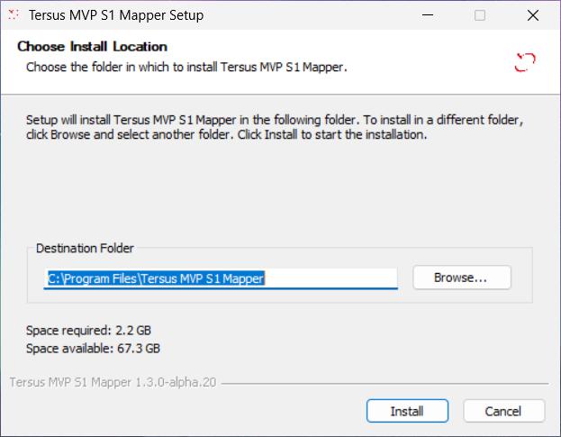
Figure: Software Installer
5.2.2 Software Update
When a new version is available, a popup will prompt you to update. Click Update Now to proceed.
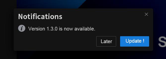
Figure: Client Update Interface
5.2.3 Software Uninstallation
Locate the installer directory on Windows and double-click Uninstall Tersus MVP S1 Mapper.exe to begin uninstallation.
[]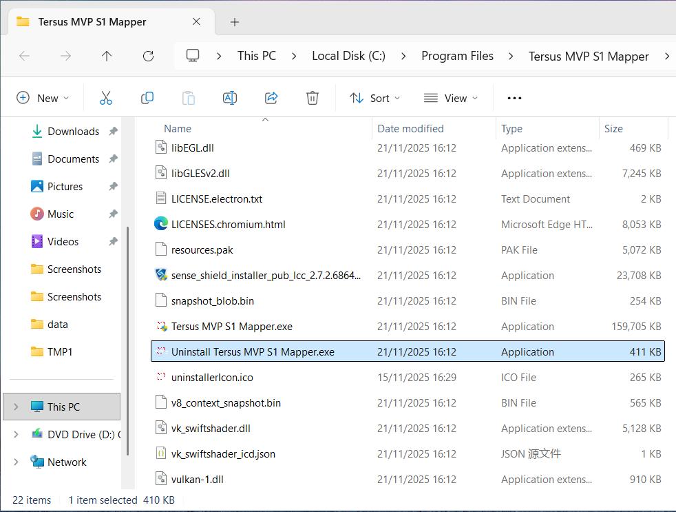
Figure: Software Uninstaller
Click Uninstall in the interface to start the process. Wait until the progress bar completes, then click Finish to complete the uninstallation.
[]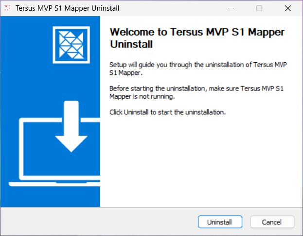
Figure: Uninstall Interface
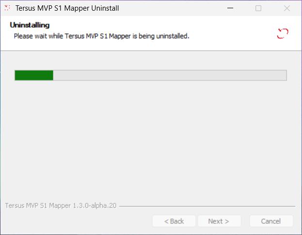
Figure: Uninstall Progress
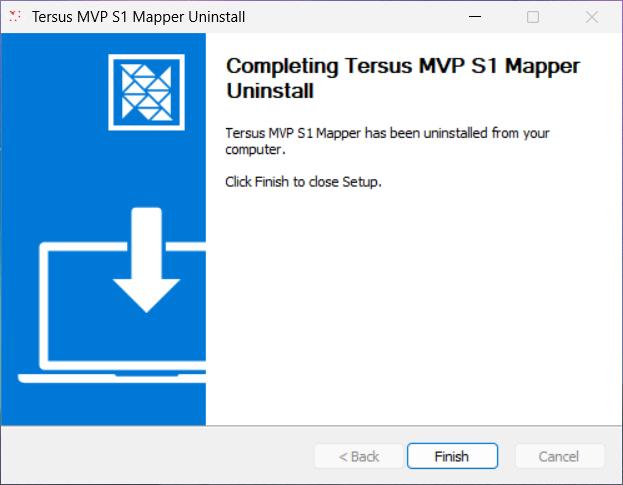
Figure: Uninstall Completion
Software Licensing
Tersus MVP S1 Mapper uses a hardware key ("dongle") for licensing. Before use, obtain the dongle and install the driver.
5.3.1 Dongle Acquisition
Each device comes with a standard dongle. For additional dongles, contact the sales team.
5.3.2 Driver Installation
After software installation, the dongle driver installation window will appear, or you can run sense_shield_installer_pub_2.6.0.64252.exe from the software directory.
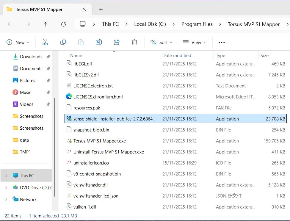
Figure: Dongle Driver Installer
Click Install Now and wait for the driver installation to complete.
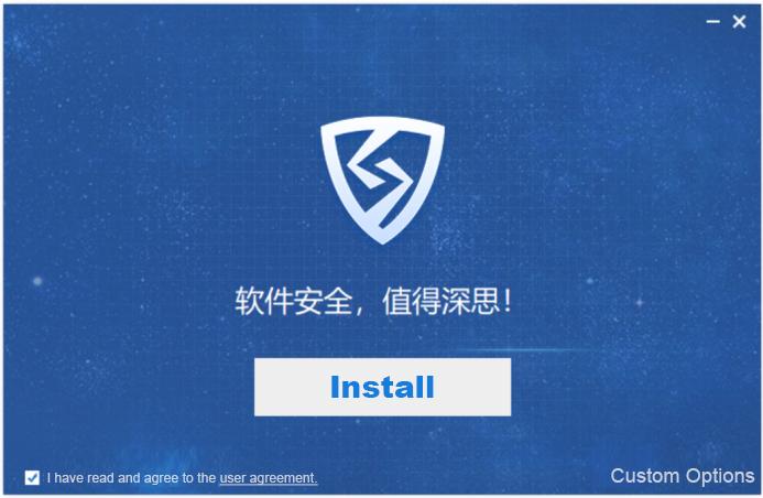
Figure: Dongle Driver Installation Interface
5.3.3 License Information
[Insert the dongle into your computer, open the Virbox user tool, and check the [Hardware Key] -- Local Dongle list to view license information.]
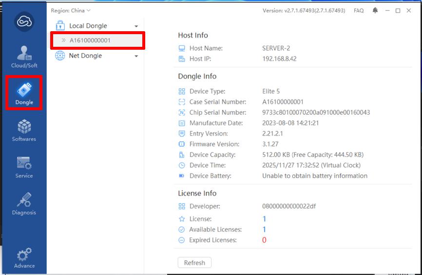
Figure: License Information Interface
\
User Registration and Login
When first using Tersus MVP S1 Mapper, a login window will appear. Log in with your Tersus GNSS account to use the software. If you do not have an account, register first. After the initial login, subsequent launches will skip the login step.
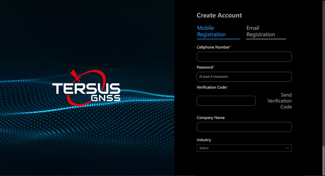
Figure: Tersus MVP S1 Mapper Registration Interface
Software Data Processing
Remove the TF card from the scanner and insert it into a card reader connected to your computer. Copy the raw scan data to your local machine. Open Tersus MVP S1 Mapper, select the copied data, and click Confirm to begin processing.
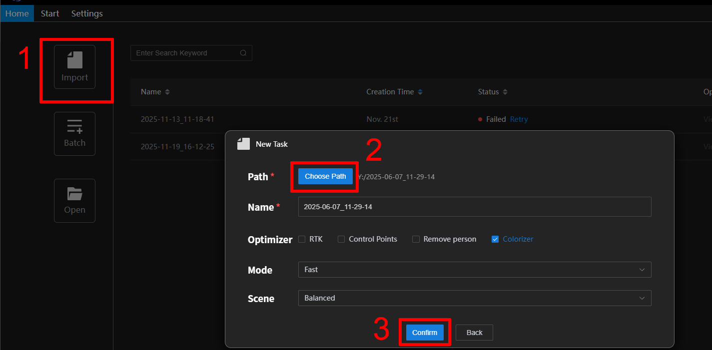
Figure: Tersus MVP S1 Mapper -- New Task
Batch import is also supported by selecting Batch Import and adding multiple data paths.
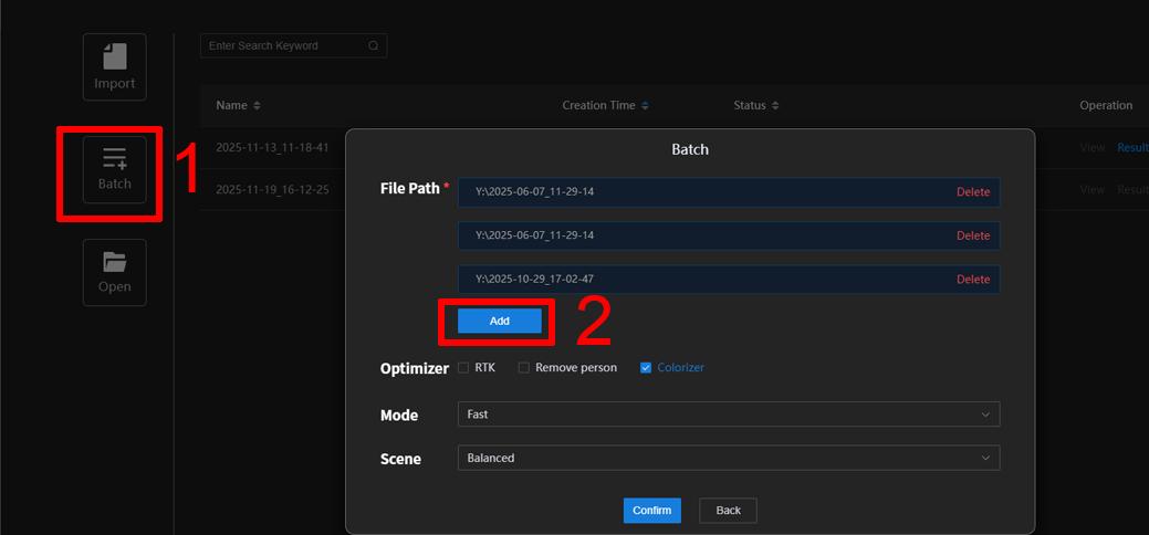
Figure: Tersus MVP S1 Mapper -- Batch Import
Once data is successfully imported, click Start Processing. The status bar shows the processing progress. After rendering, the data will be marked as Processed. Select View on the right to inspect the processed point cloud.
\
Processed Data] [
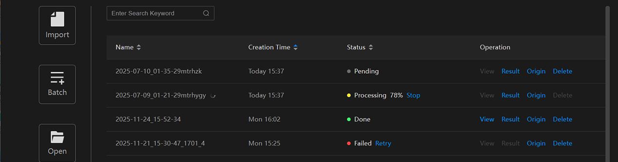
Figure: Tasks in Tersus MVP S1 Mapper
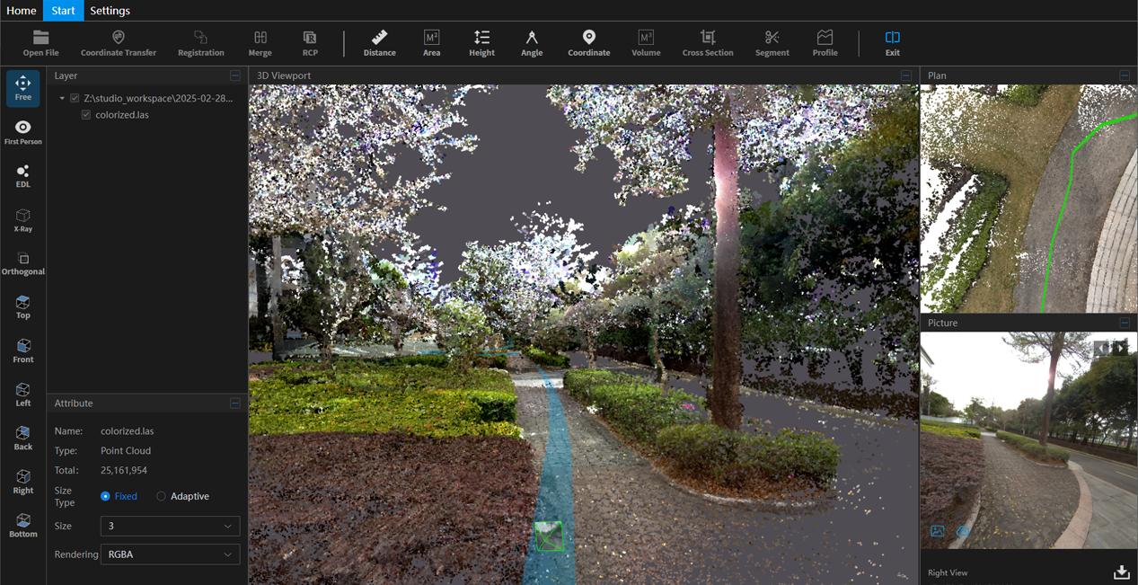
Open a completed task to view the results. Adjust the point cloud display as needed using the left toolbar. The right panel shows the corresponding plan view and captured photos in sync.
 []
[]
Figure: Point Cloud Result Interface
\
Software Window Overview
5.7.1 Layer Window
Displays loaded point cloud files or data in a tree structure, making it easy to manage and operate on multiple files or datasets.
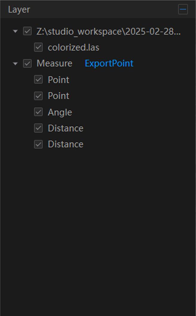
Figure: Layer Window
\
5.7.2 Show/Hide Layers
Click the small checkbox in front of a layer to toggle its visibility. When checked, the layer's data is displayed in the 3D viewport.
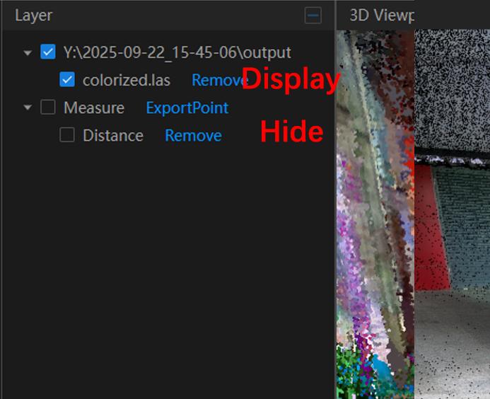
Figure: Layer Show/Hide Control
5.7.3 Remove Layer
Click Remove next to a layer to delete the current layer from the viewport.
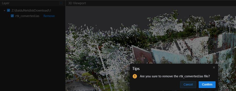
Figure: Remove Layer
\
5.7.4 Rename Layer
Select the layer to rename, right-click, and choose Rename.
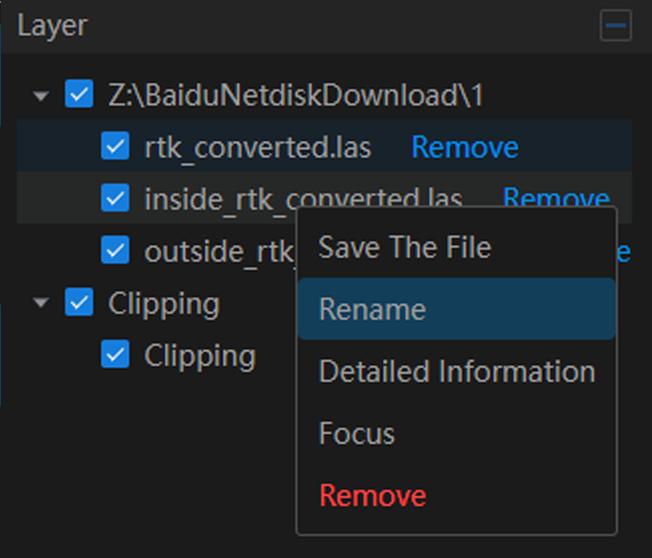
Figure: Rename Layer
Enter the new name in the popup window and click OK to confirm.
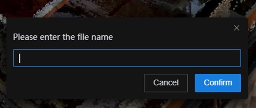
Figure: Rename Layer
\
5.7.5 Properties Window
Shows detailed properties of the selected layer or data from the Layer Window. Users can interactively adjust layer attributes.
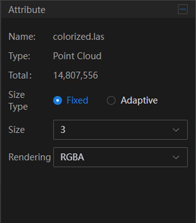
Figure: Properties Window
Select a point cloud layer to view its detailed properties and modify its settings.
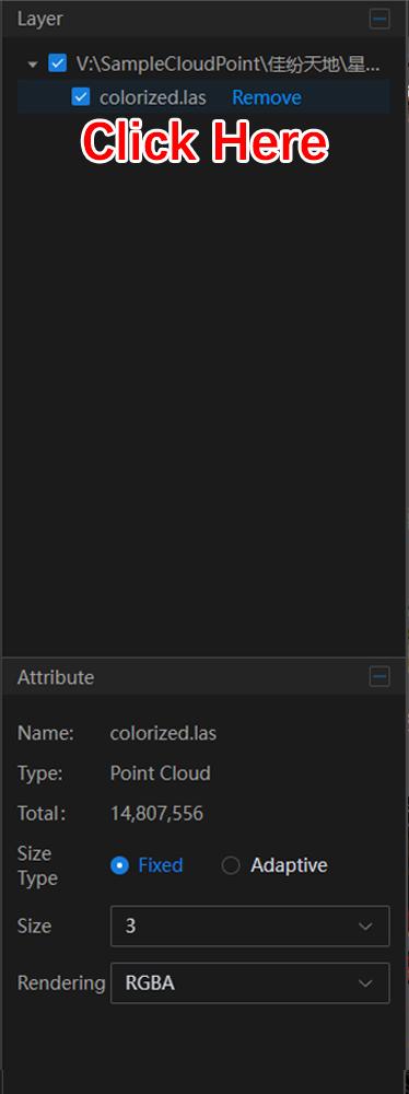
Figure: Properties Window
• Name: The point cloud file name.
• Type: File or data type; displayed as "Point Cloud".
• Point Count: Number of points in the current file.
• Size Type: Controls display size in the scene. Select Fixed to manually adjust size under Point Cloud Size, or Adaptive to automatically scale.
• Point Cloud Size: Adjusts the display size in the 3D scene.
• Rendering Mode: Sets the point cloud rendering style. Default is True Color, optional modes include Elevation and Intensity.
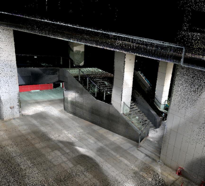
Figure: True Color Rendering
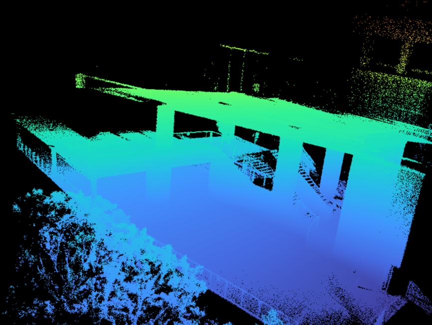
Figure: Elevation Rendering
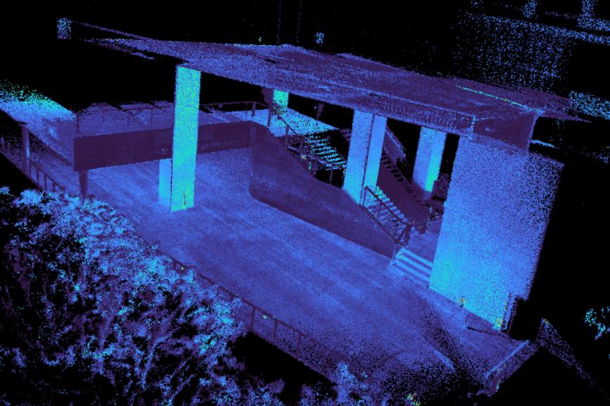
Figure: Intensity Rendering
\
Measurement Properties:Select the Measurement layer to view measurement results. Results can be copied for reporting or analysis.
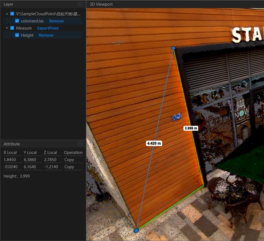
Figure: Distance Measurement Properties
\
5.7.6 3D Viewport
The 3D viewport is the main window for displaying point clouds. It supports interactive 3D visualization.
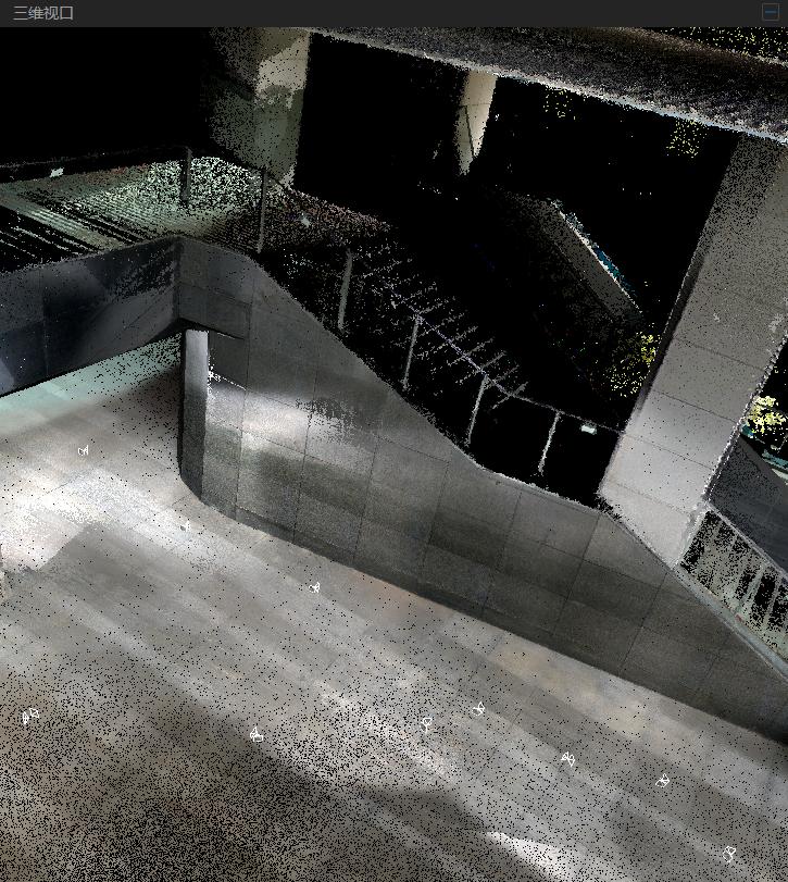
Figure: 3D Viewport
Mouse operations:
• Pan: Hold the left mouse button and drag to pan.
• Rotate: Hold the right mouse button and drag to rotate.
• Zoom: Scroll the mouse wheel to zoom in/out, centered on the cursor location.
Note: The Viewport Control Toolbar can also be used to manage the 3D view (see Section 5.8).
\
Viewport Control Toolbar
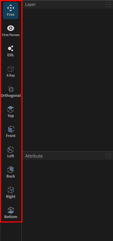
Figure: Viewport Control Toolbar
\
5.8.1 Free View / First-Person View
Free View: Use the mouse to navigate the 3D viewport (pan, zoom, rotate).
First-Person: Use the keyboard to navigate the 3D viewport:
[W: Move forward] [S: Move backward] [A: Move left]
[D: Move right] [Q: Move down] [E: Move up]
5.8.2 Orthographic / Perspective View
Default mode is Perspective. Click Orthographic to switch to an orthographic view.
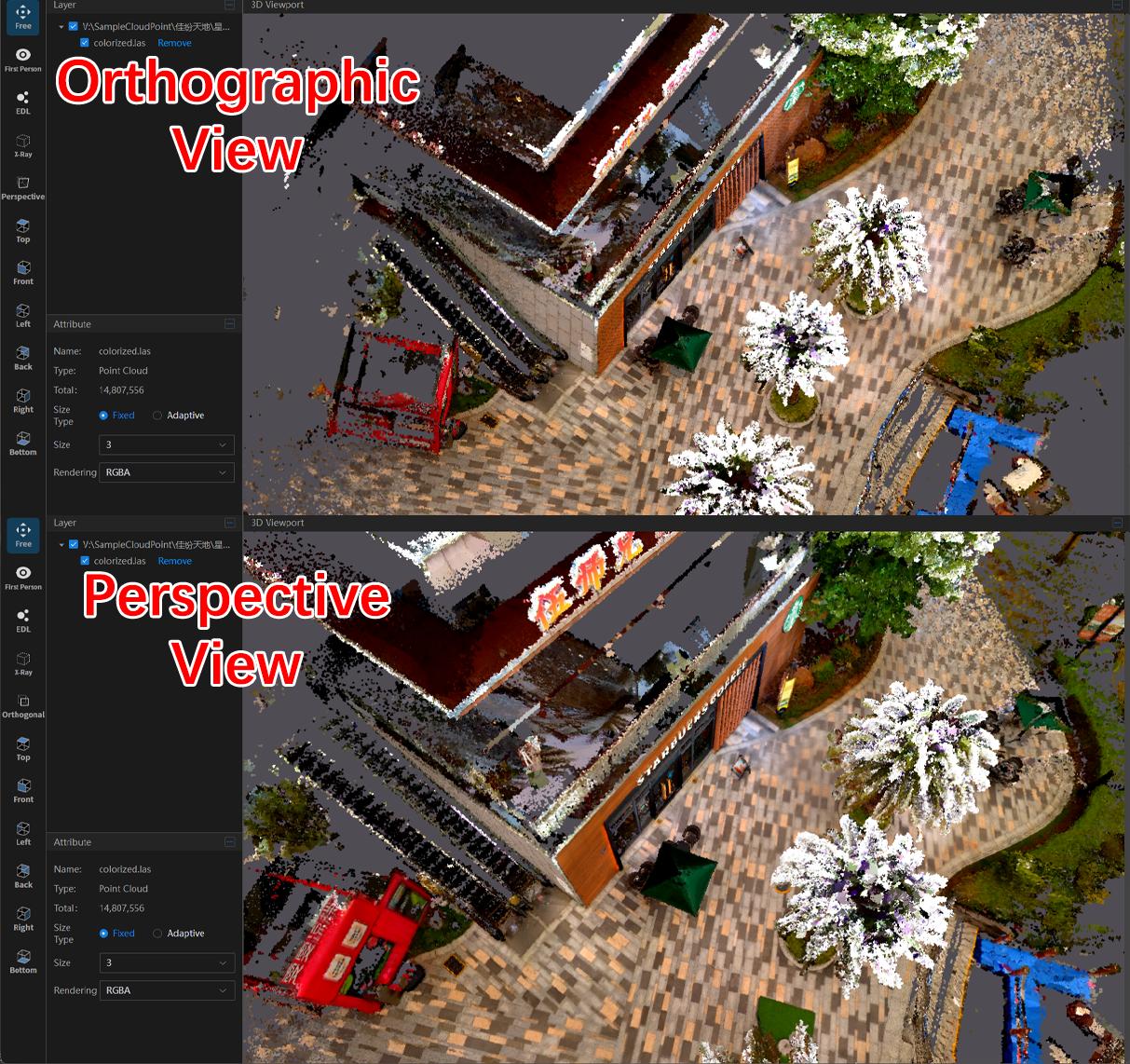
Figure: Different View Modes
5.8.3 EDL Effect
Enhances visual depth and contour clarity by simulating lighting, making model details more prominent.
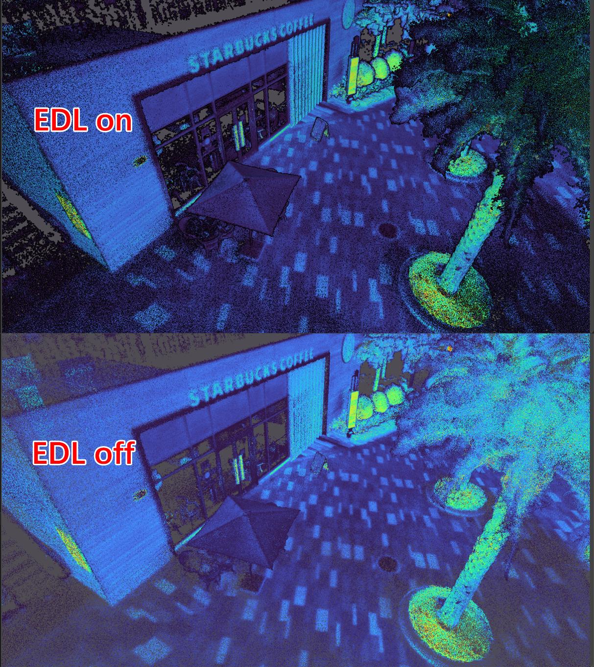
Figure: EDL Effect Comparison
\
5.8.4 Translucent View
Simulates an X-ray effect, allowing inspection of the model's internal structure.
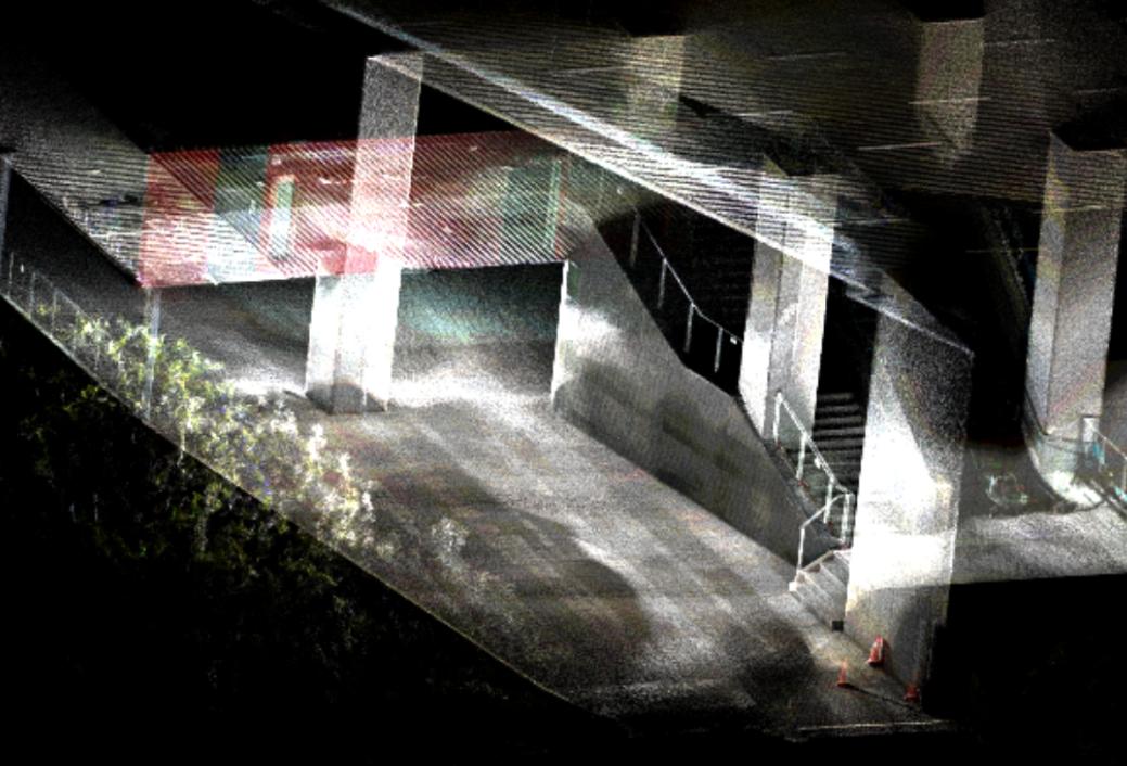
Figure: Translucent View Enabled
5.8.5 View Orientation
Control the camera to view the point cloud from different angles: Top, Front, Left, Right, Bottom, Back.
Tools Menu
The Tools Menu provides common functions such as coordinate transformation, point cloud registration, measurement, height profile analysis, clipping, point cloud comparison, and photo comparison.
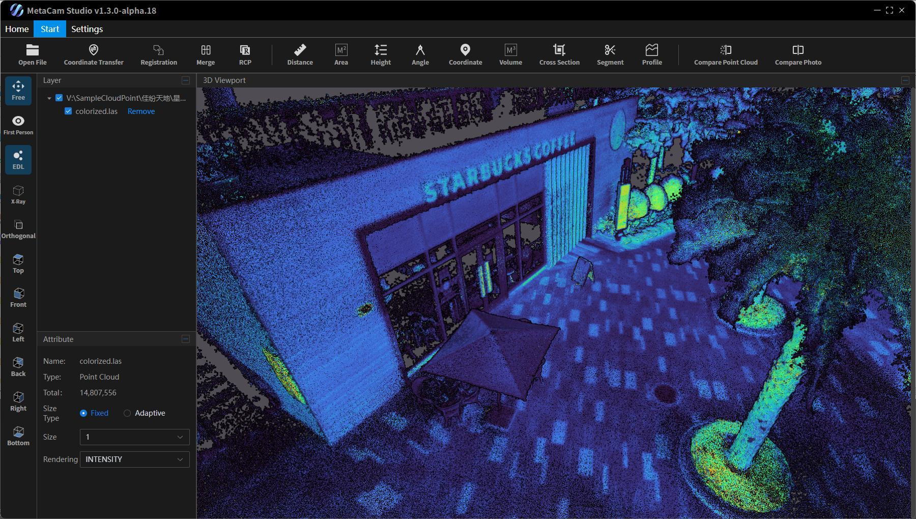
Figure: Tools Menu Bar
5.9.1 Coordinate Transformation
Click Coordinate Transformation to open the operation interface. Here, users can select the point cloud file to be transformed, the source coordinate system, the target coordinate system, the projection type, geoid file, and horizontal correction file. Finally, select the output folder and confirm to complete the transformation. Ensure the source coordinate system matches the one used during scanning.
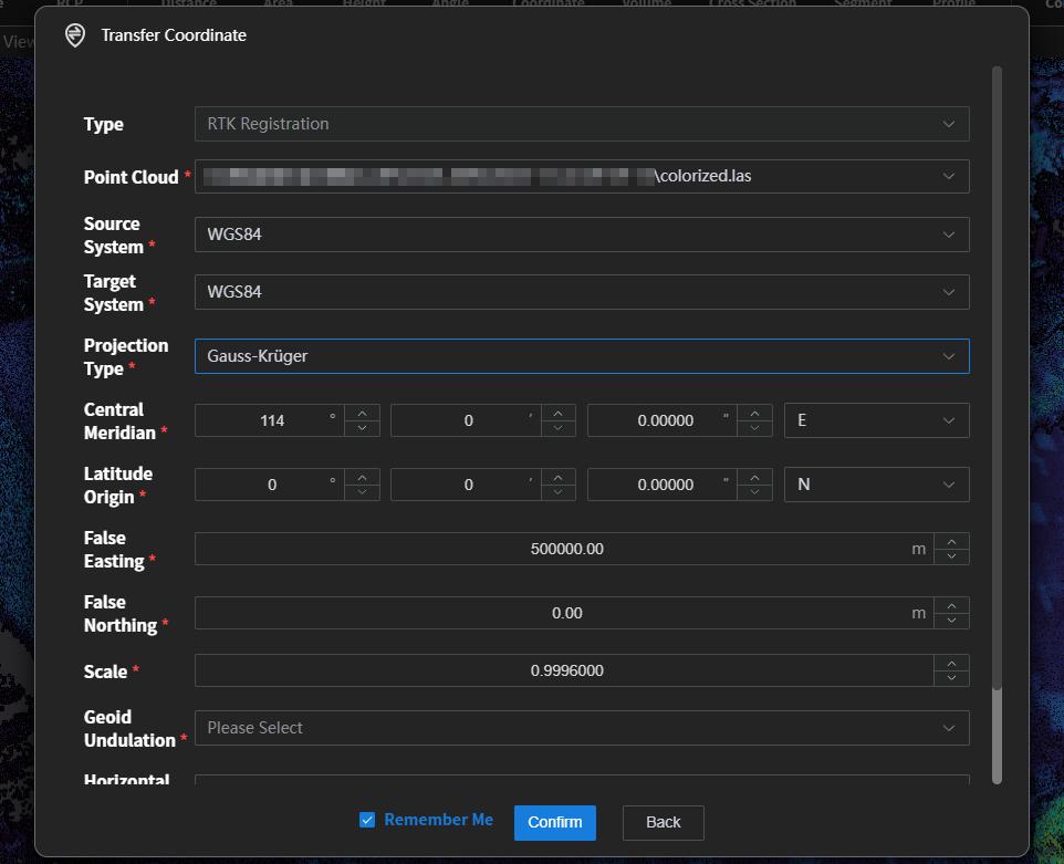
Figure: Coordinate Transformation Interface
After setting the parameters, click Confirm. The system automatically performs the transformation. Transformed data is saved in the geo folder under the results directory. The output .las files prefixed with RTK contain real-world coordinates.


Figure: Point Cloud with Real Coordinates
5.9.2 Point Cloud Registration
Click Point Cloud Registration, and select the two point clouds to be registered. Each must have at least three common points to serve as reference points.

Figure: Import Two Point Clouds for Registration
After import, choose one point cloud as the reference, optionally using an intensity point cloud. Click corresponding points in both point clouds to select reference points. The points should be clear and easy to select. Pre-plan reference points before scanning, extending scanning time at these positions if needed. It is recommended to select at least three non-collinear points.
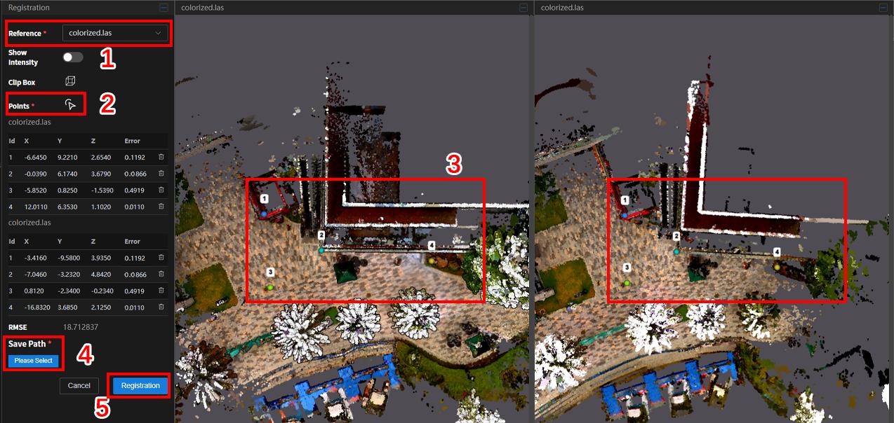
Figure: Select Common Points for Registration
5.9.3 Point Cloud Merging
Click Point Cloud Merge, select the previously registered point clouds, and click Confirm to merge them.

Figure: Point Cloud Merge Interface
\
5.9.4 RCP Conversion
When exporting point clouds to third-party software for industry-specific workflows, .las files sometimes need to be converted to .rcp. The platform integrates an RCP conversion tool for quick workflow compatibility. Click RCP, import the file, choose the save location, and click Confirm.
[]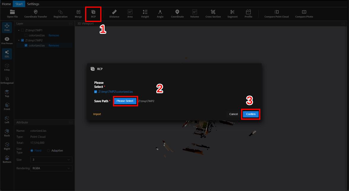
Figure: RCP Conversion Interface
5.9.5 Distance Measurement
Click Distance (Measure) to enable distance measurement. Click two points in the scene to measure the distance between them. Verify selected points for accuracy to avoid errors.
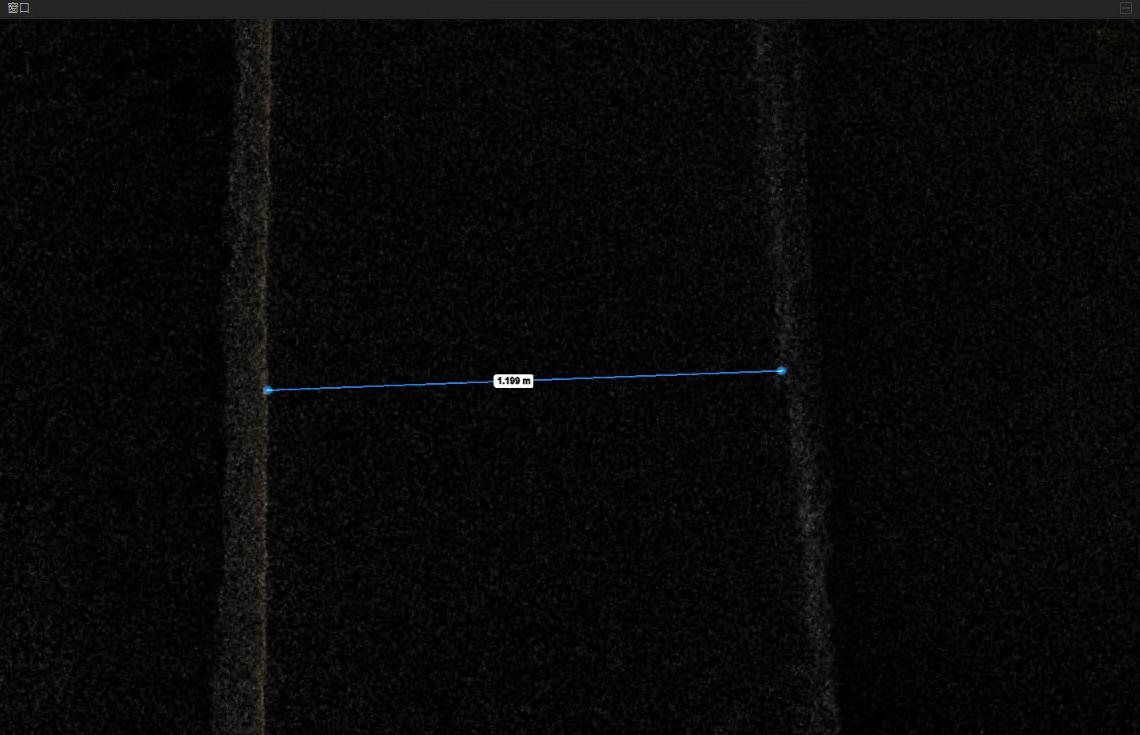
Figure: Distance Measurement
5.9.6 Area Measurement
Click Area (Measure) to measure the area of a polygon. Click points sequentially in the scene to define the polygon, and the area will be calculated automatically.
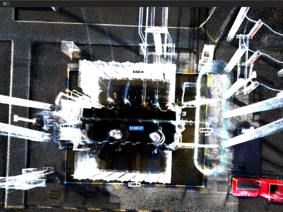
Figure: Area Measurement
5.9.7 Height Measurement
Click Height (Measure) to measure height between two planes. The platform calculates height using geometric relationships.
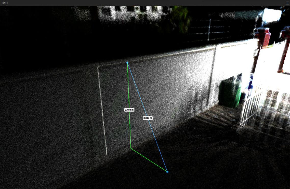
Figure: Height Measurement
5.9.8 Angle Measurement
Click Angle (Measure) to measure angles. Click points sequentially to measure the angle between two edges.
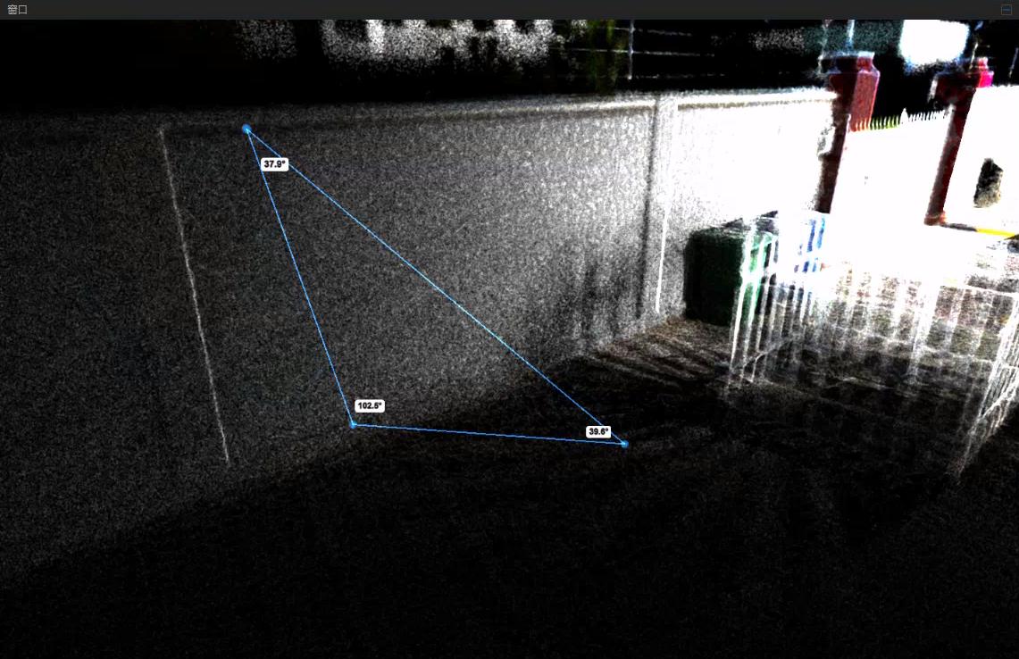
Figure: Angle Measurement
5.9.9 Coordinate Measurement
Click Position (Measure) to enable coordinate measurement. Select a point in the point cloud, and the cursor will display its coordinates.
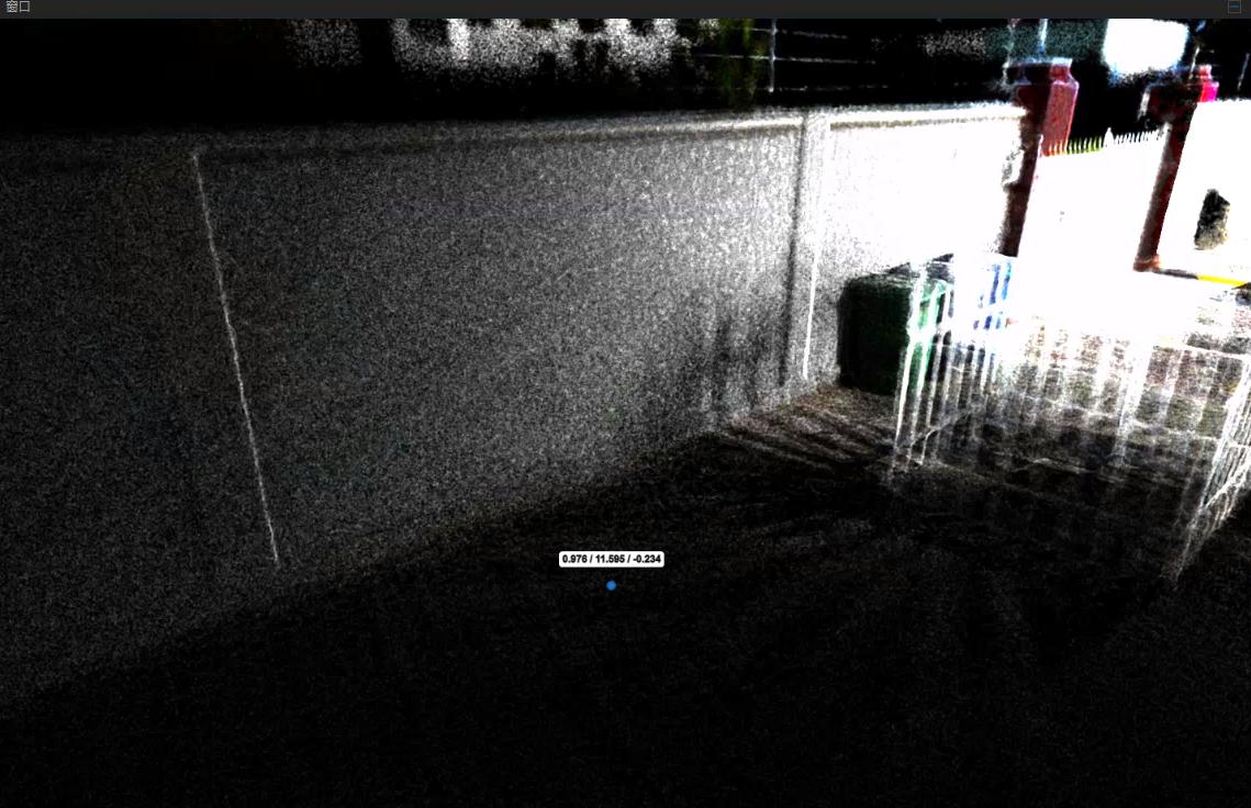
Figure: Coordinate Measurement
5.9.10 Volume Measurement
Click Volume (Measure) to calculate the volume of a selected area. The system automatically determines height range, reference height, and grid size. Click Calculate to complete the measurement.
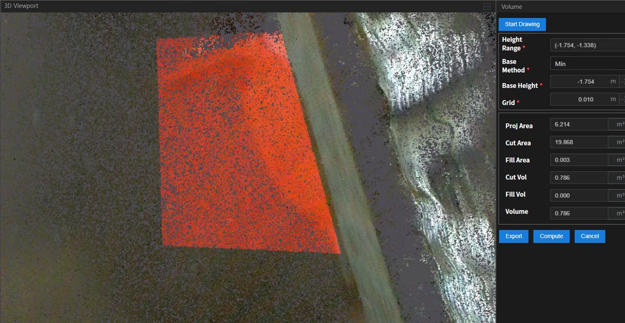
Figure: Volume Measurement
5.9.11 Cross Section
Click Cross Section to enclose the entire point cloud. Selecting the ring allows rotation along three axes. Selecting the arrows enables push/pull movement along six directions. Points outside the box are clipped; points inside are retained. Fine adjustments can be made using the box parameters on the right panel:
-
[X, Y, Z: Center position of the box]
-
[Scale X, Y, Z: Offset in three directions]
-
[Rotation X, Y, Z: Rotation around three axes]
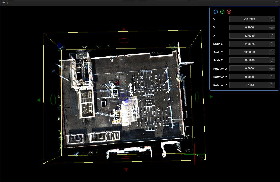
Figure: Cross Section Interface
5.9.12 Segment
Click the Segment button. Use the left mouse button to draw the region and right-click to finish drawing.
After completing the drawing, click Inside to display only the point cloud within the drawn area, or click Outside to retain only the point cloud outside the drawn area.
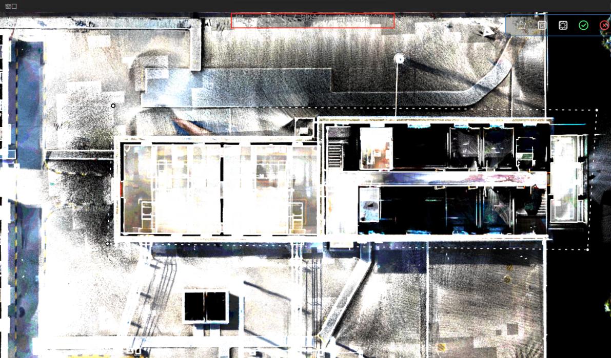
Figure: Segment Interface
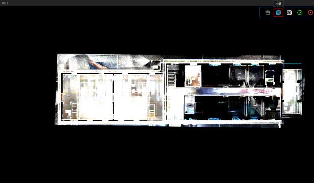

Figure: Clipping Inside / Outside
After selection, click Export. Two point clouds representing inside and outside the drawn area appear in the data frame. Right-click to save the desired point cloud.

Figure: Save Clipped Point Cloud
5.9.13 Compare Point Clouds
Click Compare Point Clouds and select two point clouds for comparison. The display is divided into left and right panels. Moving one point cloud moves the other synchronously. Clicking the small lock in the middle disables synchronization. This feature clearly highlights differences between the two point clouds.
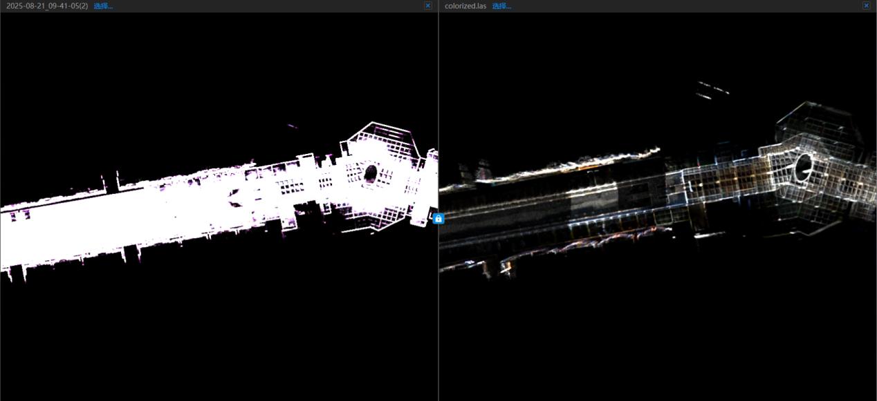
Figure: Point Cloud Comparison Interface
5.9.14 Compare Photos
[This function allows comparison between point clouds, floor plans, and site photos for analysis.]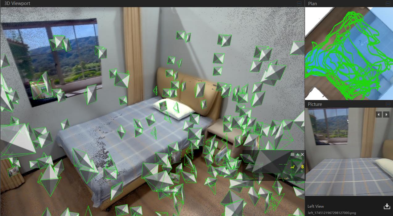
Figure: Photo Comparison Interface
\