Scanning Operation
To start scanning, the Tersus MVP S1 must be controlled using the companion Tersus MVP S1 Capture app. Through the app, users can initiate and stop scans, manage data, and perform other operations. The indicator light located beneath the RTK antenna on the scanner displays different colors to indicate the device's operating status during scanning.
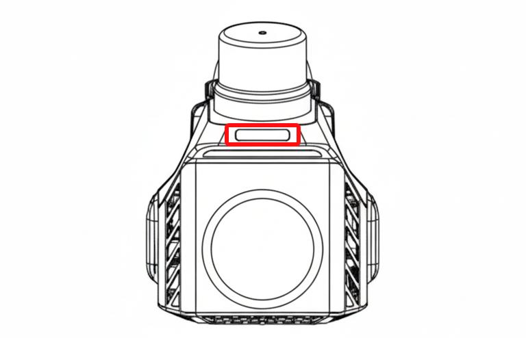
Figure: Indicator Light Location
[Indicator Color] [Operating Status]
[Yellow] [Powering on, initializing, or saving data]
[Green] [Normal scanning operation]
[Blue] [Ready, task initialization in progress]
[Red] [No TF card inserted or device malfunction]
\
Powering On
When the device is powered off, briefly press the battery button to check the number of indicator lights lit, which indicates the remaining battery level. The battery button, located at the bottom of the handle, also serves as the power indicator. Press and hold the battery button to turn on the device. When the battery indicator lights up, the handle powers the scanner. A steady battery indicator means the Tersus MVP S1 is powered on. The number of lights indicates the remaining battery level as follows:
[Number of Lights] [Battery Level]
[Red Light] [15%]
[1 Light] [5%--25%]
[2 Lights] [25%--50%]
[3 Lights] [50%--75%]
[4 Lights] [75%--100%]
Device Startup
After powering on, the Tersus MVP S1 performs a self-check to ensure all modules are functioning properly in preparation for scanning. When the indicator lights remain steady, the self-check is complete, and the device is ready for operation.
Connecting to the App
You can scan the provided QR code to download and install the app.
[]
On the main app interface, if the icon on the left side is gray, it indicates that the phone is not yet connected to the device. Tap the icon to go to the phone's Wi-Fi settings. Select the Wi-Fi network named after the device SN number. The default Wi-Fi password is 123456789. This Wi-Fi is broadcast by the Tersus MVP S1 to establish a connection with the phone. When the left icon in the app changes from gray to color, it indicates that the device is successfully connected.
[]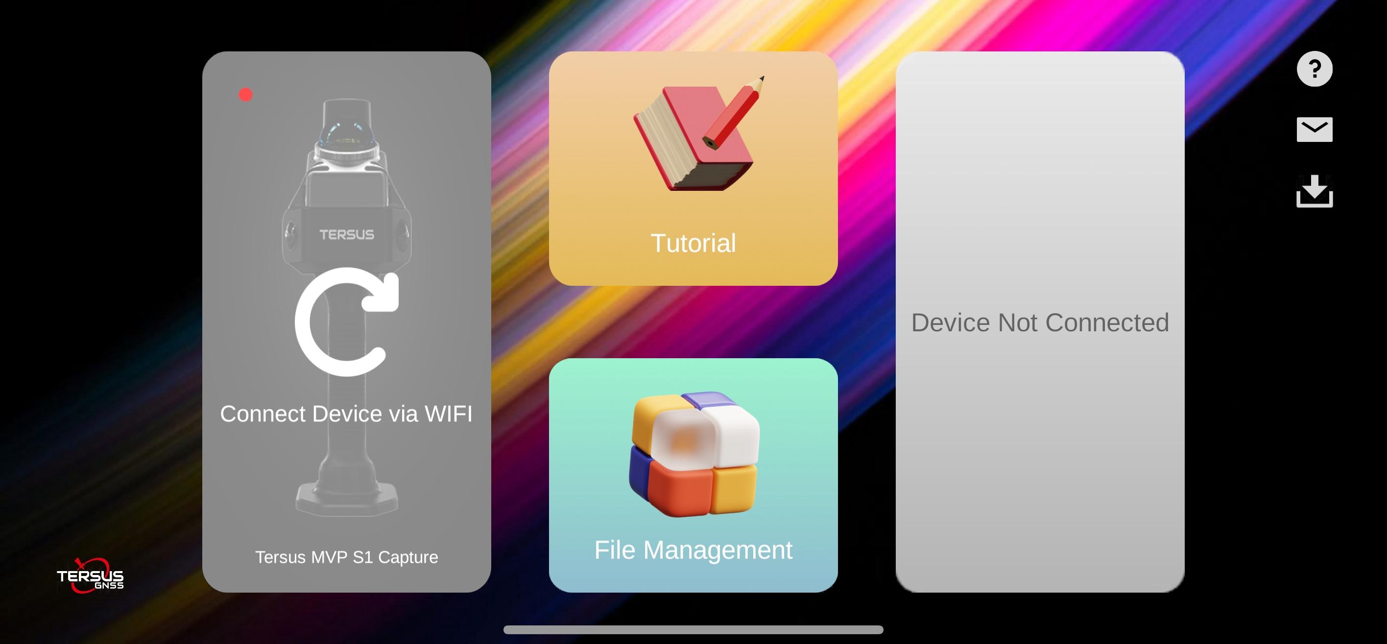
Figure: App Main Interface
Starting a Scan
Once the device is connected, tap Start Job to enter the scanning interface. Users can adjust relevant parameters before beginning the scan according to their needs.
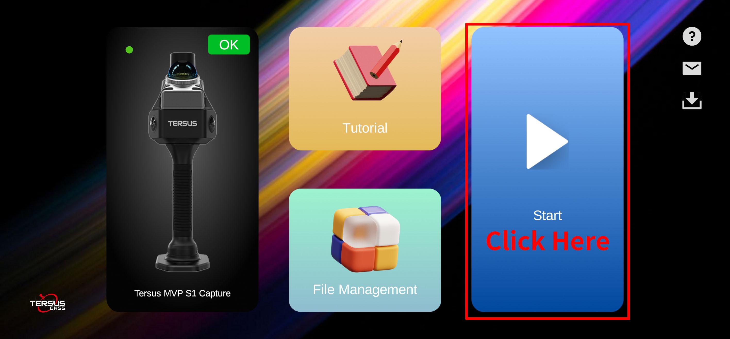
Figure: Tap Button to Enter Job Interface
Parameter Settings
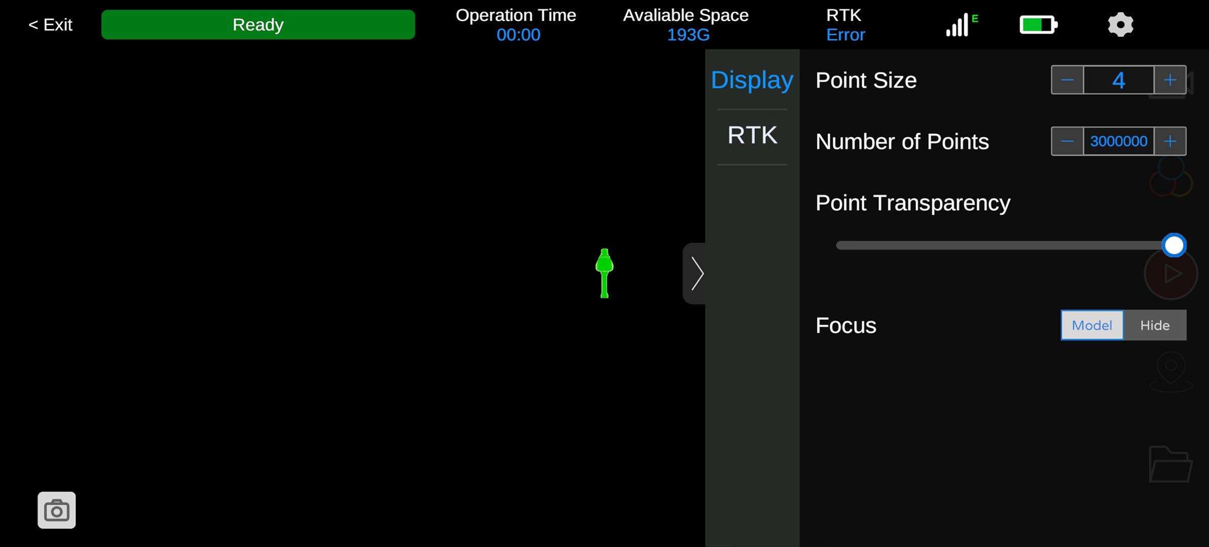
Figure: Parameter Settings Interface
Tap the Settings button on the right side of the app to configure point cloud display, RTK, and other options.
[Display Settings] [Point Cloud Size] [Adjustable from 1 to 10]
                          [Point Cloud Quantity]   [Selectable from 0 to 4 million points]

                          [Transparency]           [Adjustable from 0 to 100]

                          [Focus]                  [Allows the user to show or hide the model following the viewport]
[RTK] [RTK On/Off Button] [Controls the RTK function. Users can input RTK account credentials, supporting NTRIP protocols.]
3.5.1 RTK Settings
Enable RTK to connect to a network CORS account, supporting NTRIP or QXWZ protocols. Using RTK outdoors significantly improves data acquisition accuracy. It is recommended to enable this function.
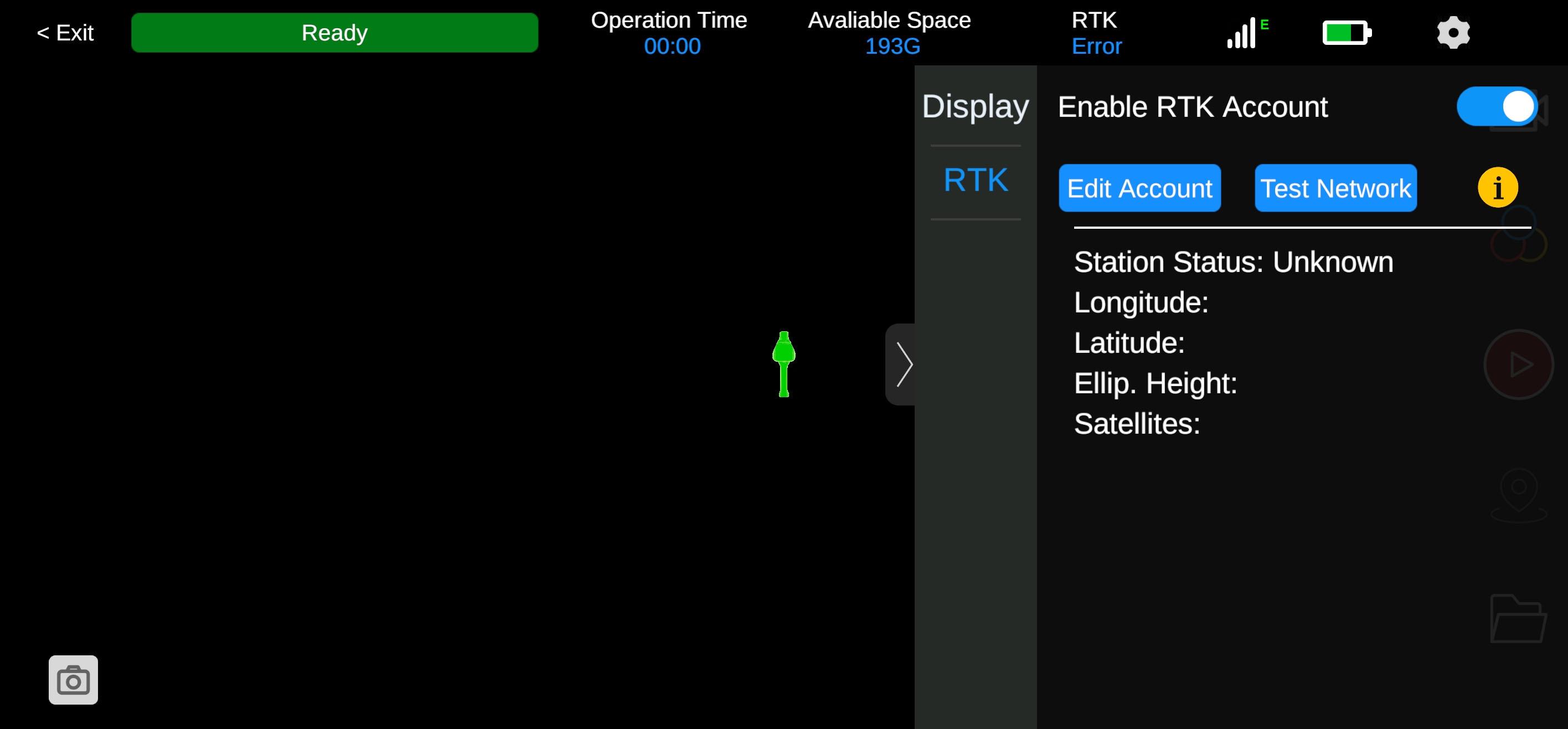
Figure: RTK Settings Interface
Creating a New Project
When the device status shows Ready, tap the Start button on the right side to begin a new job.
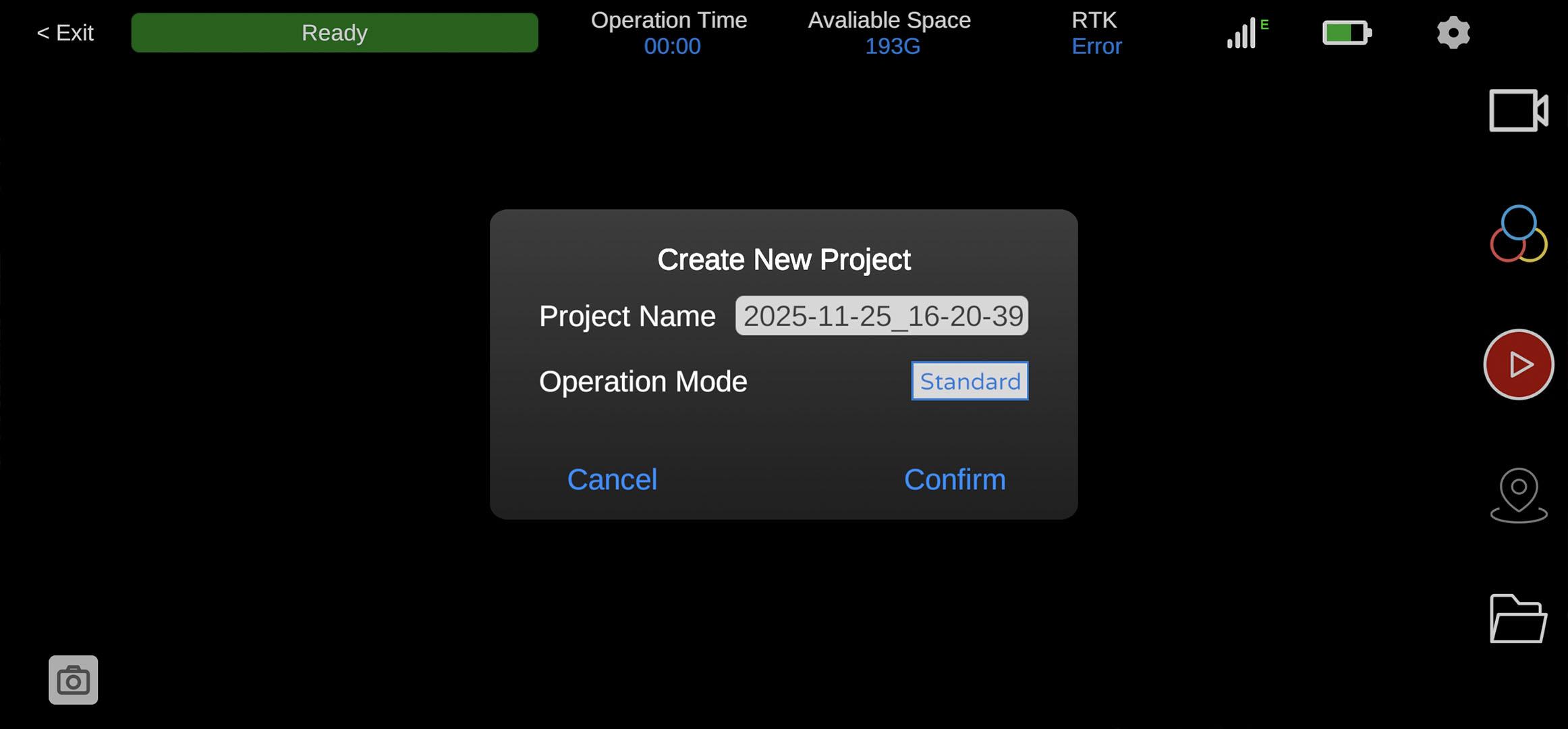
Figure: New Project Interface
A New Project dialog will appear. Enter the project name, select the job mode (Standard or 3DGS), and set the photo interval. Tap Confirm to start. The top of the screen will display device status, working time, storage capacity, RTK status, signal strength, and battery level.
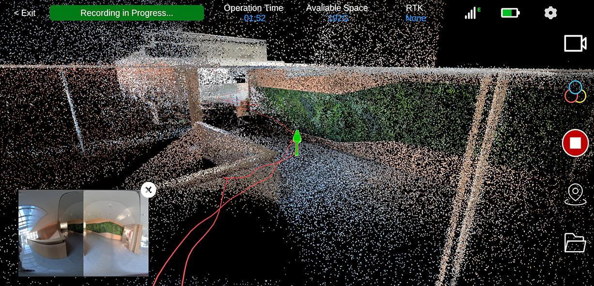
Figure: Data Acquisition Interface
Control Point Collection
During a job, tap the second button at the bottom right of the interface to add or remove control points. Control points are used during post-processing to calibrate and improve the overall accuracy of collected data.
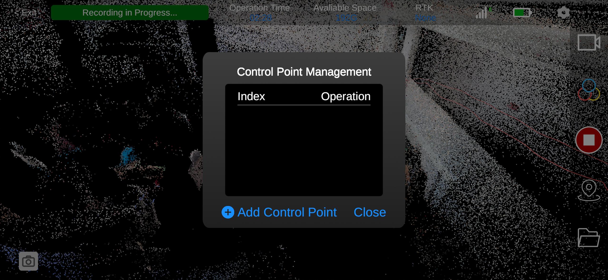
Figure: Control Point Interface
When collecting a control point, align the center of the positioning plate's control point area with the location to be added, then tap Add Control Point. Keep the device stable for approximately 10 seconds to complete the collection.
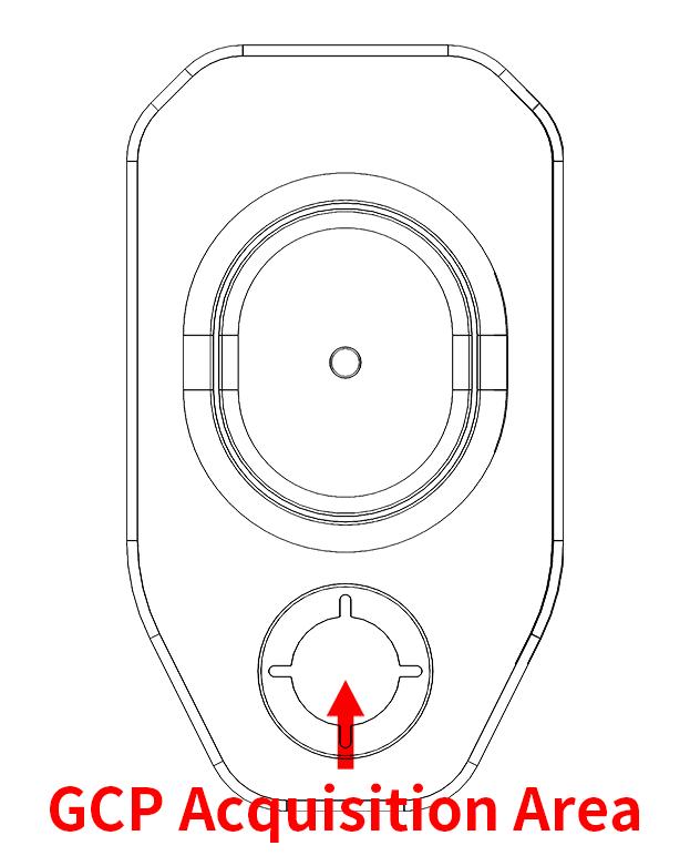
Figure: Align Positioning Plate with Control Point
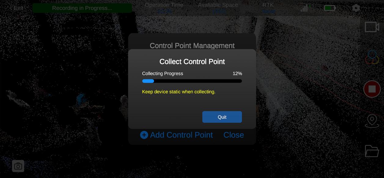
Figure: Do not move the device until the progress is complete.
Users can edit, overwrite, or delete control points after they are set, according to operational needs.
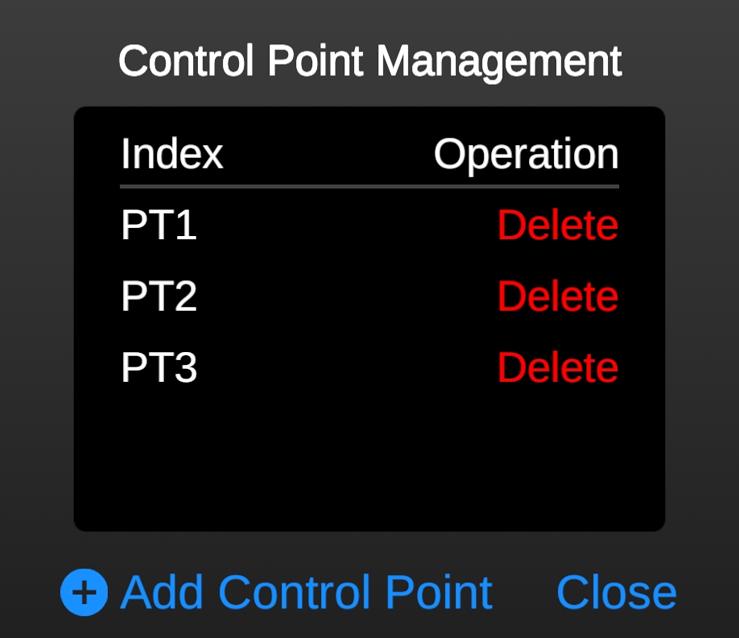
Figure: Control Point Editing Interface
Data Acquisition
When the device status shows Ready, scanning can begin. The software displays the reconstructed 3D point cloud and collection trajectory in real time, and users can manually inspect the 3D colorized point cloud.
\
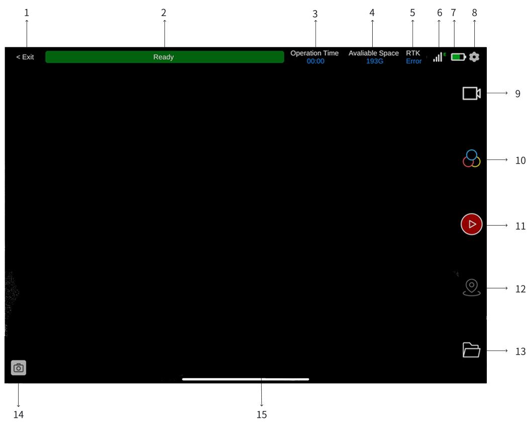
The functions of the job interface are as follows:
-
[Return to Main Interface: Tap to return to the app's main interface.]
-
[Status Indicator: Displays the current job status.]
-
[Job Time: Shows the elapsed time for the current project.]
-
[Storage: Displays the remaining memory space.]
-
[RTK Status: Shows the status of the RTK module.]
-
[Signal: Displays the device's current signal information.]
-
[Battery Level: Indicates the device battery status.]
-
[Settings: Opens the job parameter settings.]
-
[Roaming Mode: Switches between free roaming and third-person view modes.]
-
[Point Cloud Mode: Switches the 3D scene display between colorized point cloud, intensity-colored, and elevation-gradient modes.]
-
[Start/Stop: Controls the start and end of a job.]
-
[Control Point Management: Allows adding, deleting, or overwriting control points. Adding control points improves the overall accuracy of the collected data during post-processing.]
-
[File Management: Opens the file management page to manage, delete, view, or download device or local project data.]
-
[Photo Points: Displays photos captured by the device in real time. By default, one photo is taken every 0.5 seconds.]
-
[3D Scene: Displays the point cloud in real time. Users can zoom, pan, or rotate to inspect details of the 3D scene.]
\
Scanning Notes
-
[Before starting a scan, inspect the lenses for smudges or fingerprints to avoid affecting data quality.]
-
[When creating a new project, place the device on a level surface and keep it stationary during initialization to prevent model displacement.]
-
[During scanning, it is recommended to move the device at a speed of approximately 1 m/s. Avoid large arm movements to prevent incomplete or distorted data.]
-
[Although the device filters moving objects, avoid keeping people in front of the scanner for prolonged periods, as this may reduce the quality of collected data.]
-
[During the scanning process, use the app to monitor the live view to check for missed areas or important objects and perform supplementary scanning if needed.]
-
[When moving from an area with reference objects to a very open space (for example, entering a balcony from a high-floor interior), the LiDAR may not have sufficient reference points, which may result in differences in the collected data.]
Saving Data
To end a scan, tap the red button on the right side of the screen. After approximately 10 seconds, a Save Successful message will appear. If you wish to continue scanning, wait at least one minute after the confirmation message before starting a new scan.
Powering Off the Device
Ensure that all data has been collected and saved, and that the device is in a stopped state. Press and hold the power button on the handle for approximately 10 seconds. When the indicator lights turn off and no operational sounds are heard, the Tersus MVP S1 is fully powered off.