Equipment Installation and Dismantling
Pre-Installation Preparation
Before system installation, please check the equipment against the packing list to ensure all components are complete
NO Item Name Unit Quantity
1 MVP 400 Scanner Unit PCS 1
2 Camera PCS 1
3 SKYPORT Adapter PCS 1
4 Antenna Component PCS 1
5 USB-disk PCS 1
6 Dongle PCS 1
7 Carrying case PCS 1
8 Certificate of quality PCS 1
9 Warranty card PCS 1
10 Product Manual PCS 1
11 Packing List PCS 1
12 Desiccant PCS 2
13 Mirror wipe PCS 4
Tab 3-1 Packing List
Remarks:
The above list is for reference only. Please refer to the packing list provided with the equipment for the actual contents.
Installation and removal of system equipment
Warning:
-
When installing the MVP400 system, handle the equipment with care to protect it.
-
During installation and dismantling, ensure the drone is turned off to avoid electrical damage to the equipment.
-
After dismantling the equipment, place all components back in their designated positions in the packaging box and check for completeness.
Standard Vibration-Damping Mount Installation and Dismantling (Take the DJI M300 Drone as an Example)
Installation of Standard Shock Absorption Bracket:
Step 1: Remove the original shock absorption bracket from the M300 and take out the standard shock absorption bracket.
Step 2: Align the four screw holes on the M300, and use an Allen wrench to tighten the four screws sequentially to complete the installation.
Disassembly of Standard Shock Absorption Bracket:
Use an Allen wrench to remove the four screws sequentially to complete the disassembly.
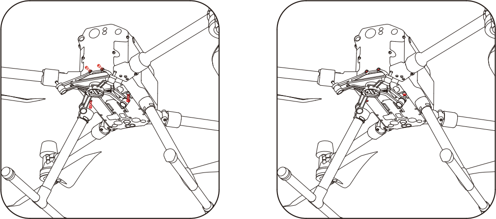
Figure 3-2 Standard Vibration-Damping Mount Installation and Dismantling
Installation and Dismantling of the Mounting Bracket and Quick-Release Interface
Installation: Align the antenna interface of the mounting bracket with the antenna interface on the quick-release, then snap it down. Rotate the mounting bracket lock cover clockwise to connect the mounting bracket with the quick-release interface
Dismantling: Rotate the mounting bracket lock cover counterclockwise to loosen it, then lift the mounting bracket upwards to detach it from the quick-release interface
Figure 3-3 Installation and Dismantling of the Mounting Bracket and Quick-Release Interface
Installation and Dismantling of the Main Unit and Standard Vibration-Damping Mount
Installation: Align the white circular marking on the main unit with the corresponding circular marking on the drone mount. Once aligned, rotate the main unit counterclockwise as indicated in the diagram. The red circular marking on the SKYPORT adapter should align with the circular marking on the drone mount. When you hear a "KA" sound and the device cannot be rotated, the installation is complete
Dismantling: Align the red circular marking on the main unit with the corresponding circular marking on the drone mount. Press the button marked with an arrow, then rotate the device counterclockwise as indicated in the diagram. When the white circular marking on the SKYPORT interface aligns with the circular marking on the drone mount, the device can be removed, completing the dismantling process.
Figure 3-4 Installation and Dismantling of the Main Unit and Standard Vibration-Damping Mount
Installation and Dismantling of the Slide Rail Adapter and Quick-Release Interface
Installation: Align the antenna interface of the slide rail adapter with the antenna interface on the quick-release, snap it downward, and rotate the slide rail adapter lock cover clockwise to complete the installation.
Dismantling: Rotate the slide rail adapter lock cover counterclockwise to loosen it, then lift the slide rail adapter upwards to complete the dismantling
Foto 3-5 Installation and Dismantling of the Slide Rail Adapter and Quick-Release Interface
Installation and Dismantling of the Universal Vibration-Damping Mount and UAV (Take a Quadrotor Drone as an Example)
Installation:Align the four installation holes of the universal vibration-damping mount with the mounting holes on the drone, then tighten the screws to complete the installation.
Dismantling:Remove the four screws from the universal vibration-damping mount to complete the dismantling.
Foto 3-6 Installation and Dismantling of the Universal Vibration-Damping Mount and UAV
Installation and Dismantling of the Main body and Universal Vibration-Damping Mount
Installation:Align the connector of the main unit's quick-release section with the universal vibration-damping mount, horizontally insert it into the slide rail, and push it to the bottom. Then, rotate the handle 180° clockwise to lock the main body and slide rail. If the device cannot rotate, the installation is successful.
Dismantling:Rotate the handle 180° counterclockwise to unlock the slide rail and main unit. Then, push the main unit horizontally towards the front of the drone to detach the main body.
Foto 3-7 Installation and Dismantling of the Universal Vibration-Damping Mount and UAV
Installation & Removal of Antenna Kit
Installation of the Antenna Kit:
After mounting the device onto the drone, align the GPS antenna assembly along the direction indicated by the arrow in the diagram and insert it into the SKYPORT adapter. Then, rotate the locking mechanism clockwise to secure it, completing the installation.
Removal of the Antenna Kit :
First, loosen the locking mechanism by turning it counterclockwise, and then pull the antenna assembly upward to complete the removal.
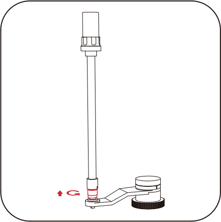
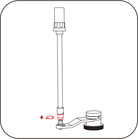
Figure 3-8 Installation & Removal of Antenna Kit