Introduction
This chapter includes overview, receiver features, and devices in the package.
1.1 Overview
TS21 GNSS receiver is an innovative integration of visual positioning technology, GNSS, IMU and dual cameras. Its front camera enables high-precision, high-efficiency and multi-point measurement, allowing you to measure what you see and generate point clouds on site. Its front and bottom cameras work in tandem to support CAD AR visual stakeout, enabling precise path planning at varying distances. Its built-in IMU ensures accuracy without any limitation on tilt angles.
With an internal high-performance multi-constellation and multi-frequency GNSS board, the TS21 GNSS receiver can provide high accuracy and stable signal detection. The high-performance antenna can speed up the time to first fix (TTFF) and improve anti-jamming performance. The built-in large capacity battery supports up to 9 hours of field work in 4G/3G/2G network and Rover radio mode. The built-in UHF radio module supports long distance communication. The rugged housing protects the equipment from harsh environments.
1.2 Receiver features
The TS21 GNSS receiver has following features:
- Supports multiple constellations & frequencies
<!-- -->
-
GPS L1C/A, L2C, L2P, L5
-
GLONASS L1C/A, L2C/A
-
Beidou B1, B2, B3 , support BDS-3
-
Galileo E1, E5a, E5b
-
QZSS L1C/A, L2C, L5
-
SBAS supports WAAS, EGNOS, GAGAN, SDCM, MSAS
<!-- -->
-
Supports 1792 channels.
-
Innovative visual positioning technology for precise measurements.
-
Measure what you see, save your time.
-
Point clouds generation and export from measurement results.
-
Dual professional cameras, visual navigation and stakeout in One step.
-
Supports 410-470MHz UHF radio, 4G network, Wi-Fi , Bluetooth, NFC.
-
Tilt compensation without calibration, immune to magnetic disturbances .
-
32GB internal storage
-
IP68-rated dust- & waterproof enclosure, for reliability in harsh environmental conditions
-
Free subscription of Tersus Caster Service (TCS): transmit the correction data from Base to Rover
1.3 Devices in the package
The devices in the package may vary according to the customer requirement. Here describes the major parts in the package.
1.3.1 TS21 GNSS receiver
The TS21 GNSS receiver is shown as below.
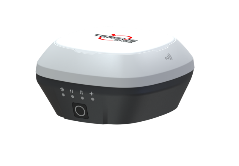
Figure 1.1 TS21 GNSS receiver
Buttons
One buttons is equipped on TS21 GNSS receiver.
[![]() ]: Power ON/OFF button. When the device is off, long press it for 2 seconds to power on the receiver. When the receiver is on, long press it for over 3 seconds to power off the receiver.
]: Power ON/OFF button. When the device is off, long press it for 2 seconds to power on the receiver. When the receiver is on, long press it for over 3 seconds to power off the receiver.
LED Indicators
Four LED indicators for TS21 GNSS receiver; smart battery with power display on the bottom. The LEDs on the front panel indicate various operating conditions. The detailed LED Descriptions are shown in the tables below.
Satellite
Correction Data
Solution
Static

Battery
Power ON/OFF
Figure 1.2 Buttons and display on TS21
Table 1.1 LED indicators
+----------------------------------------------------------------------------------------------------------------------------------------------+----------------------------------------------------------------------------------------------------------------------------------------------------------------------------------------------------------------------------------+
| LED indicator | Description |
+----------------------------------------------------------------------------------------------------------------------------------------------+----------------------------------------------------------------------------------------------------------------------------------------------------------------------------------------------------------------------------------+
| ![]() | Blue LED. No flashing indicates no satellites. Flashing indicates that it is searching satellites. If only 1-3 satellites are found, it flashes every 5 seconds. If more than 4 satellites are found, it flashes every 1 second. |
| | |
| Satellite | |
+----------------------------------------------------------------------------------------------------------------------------------------------+----------------------------------------------------------------------------------------------------------------------------------------------------------------------------------------------------------------------------------+
|
| Blue LED. No flashing indicates no satellites. Flashing indicates that it is searching satellites. If only 1-3 satellites are found, it flashes every 5 seconds. If more than 4 satellites are found, it flashes every 1 second. |
| | |
| Satellite | |
+----------------------------------------------------------------------------------------------------------------------------------------------+----------------------------------------------------------------------------------------------------------------------------------------------------------------------------------------------------------------------------------+
| ![]() | Blue LED. Flashing indicates correction data. |
| | |
| Correction data | |
+----------------------------------------------------------------------------------------------------------------------------------------------+----------------------------------------------------------------------------------------------------------------------------------------------------------------------------------------------------------------------------------+
|
| Blue LED. Flashing indicates correction data. |
| | |
| Correction data | |
+----------------------------------------------------------------------------------------------------------------------------------------------+----------------------------------------------------------------------------------------------------------------------------------------------------------------------------------------------------------------------------------+
| ![]() | Blue LED indicates static survey mode. |
| | |
| Static Survey | |
+----------------------------------------------------------------------------------------------------------------------------------------------+----------------------------------------------------------------------------------------------------------------------------------------------------------------------------------------------------------------------------------+
|
| Blue LED indicates static survey mode. |
| | |
| Static Survey | |
+----------------------------------------------------------------------------------------------------------------------------------------------+----------------------------------------------------------------------------------------------------------------------------------------------------------------------------------------------------------------------------------+
| ![]() | Blue LED. Steady blue indicates fixed solution, flashing 1Hz indicates floating solution, off light for other solutions. |
| | |
| Solution status | |
+----------------------------------------------------------------------------------------------------------------------------------------------+----------------------------------------------------------------------------------------------------------------------------------------------------------------------------------------------------------------------------------+
|
| Blue LED. Steady blue indicates fixed solution, flashing 1Hz indicates floating solution, off light for other solutions. |
| | |
| Solution status | |
+----------------------------------------------------------------------------------------------------------------------------------------------+----------------------------------------------------------------------------------------------------------------------------------------------------------------------------------------------------------------------------------+
|  | Blue LED. Steady blue in normal operation. Slow flash indicates the battery level is between 25% and 15%. Fast flash indicates the battery level is below 15% and reminds users to change battery. |
| | |
| Battery | |
+----------------------------------------------------------------------------------------------------------------------------------------------+----------------------------------------------------------------------------------------------------------------------------------------------------------------------------------------------------------------------------------+
| Blue LED. Steady blue in normal operation. Slow flash indicates the battery level is between 25% and 15%. Fast flash indicates the battery level is below 15% and reminds users to change battery. |
| | |
| Battery | |
+----------------------------------------------------------------------------------------------------------------------------------------------+----------------------------------------------------------------------------------------------------------------------------------------------------------------------------------------------------------------------------------+

Power Display
Battery Button
Figure 1.3 Smart battery with power display
Table 1.2 Power display and button
LED indicator Description
Battery Button After clicking the battery button, the green light will be on to display the current remaining power.
Power Display Green LED. Under normal circumstances, one indicator represents 25% of the power. When charging, the green light flashes to display the current charging power.
LED Flash Patterns
The possible flash patterns of various states of receiver operation are listed in the table below.
Table 1.3 Possible LED flash patterns
Receiver mode Button operation LED flash patterns
Receiver OFF Long press the power button for 3s All LEDs are off.
Receiver ON Long press the power button for 2s All LEDs are on, then all off, and each LED especially the power button starts to indicate current status after initialization.
Low power N/A Battery LED flashes slow.
Battery exhausting N/A Battery LED flashes fast.
Searching satellites N/A Satellite LED flashes.
Satellites tracked N/A Satellite LED flashes every 5s for 1-3 satellites and flashes every 1s for more than 4 satellites.
Receiving valid data packet N/A Correction data LED flashes blue at 1Hz.
Static mode N/A Static status LED is steady blue.
Fixed solution N/A Solution status LED is steady blue.
Floating solution N/A Solution status LED flashes blue at 1Hz.
Firmware upgrade N/A For Basic version, all six LEDs are on for 1s thereafter only power LED lights up, then all LEDs light up when upgrading, lights off when restarting. Then all six LEDs light up for 1s thereafter only power LED lights up means it restarts successfully with updated firmware.
Note: N/A means Not Applicable.
Receiver Ports
The bottom of TS21 receiver is shown as below.
TNC port
Type-C port
SIM slot
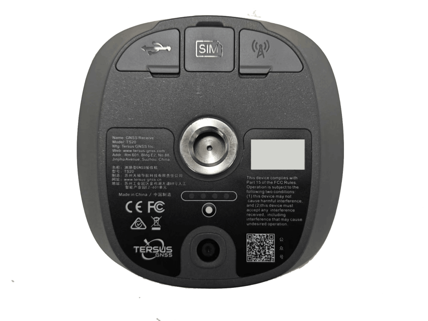
Bottom camera
Smart battery with power display
Screw hole
Figure 1.4 Bottom of TS21 GNSS receiver
Table 1.4 Receiver ports on the bottom side
Icon Name Connections
 Serial port & external power Device, computer, USB drive, external power, communication, external radio
 SIM slot Nano SIM card
 TNC port Radio antenna
 Screw hole 5/8'' x 11 UNC-2B connector for corresponding connector and pole.
1.3.2 Type-C to USB cable
Functions:
1.Connect to the USB port of computer for data downloading;
2.Firmware upgrade, details refer to section 2.4;
3.Connect to the charger adapter to charge TS21. Charge the battery completely before using TS21 for the first time. The charging takes approximately 3 hours at room temperature. If the battery has been stored for longer than three months, charge it before use.
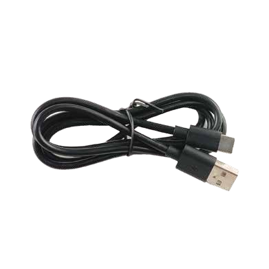
Figure 1.5 Type-C to USB cable
1.3.3 Adapter
Connect to the Type-C cable to charge TS21. The maximum power can reach 15W(5V 3A), realizing fast charging.
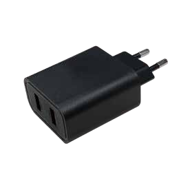
Figure 1.6 Adapter for EU
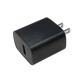
Figure 1.7 Adapter for US
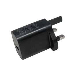
Figure 1.8 Adapter for UK
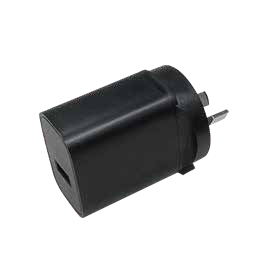
Figure 1.9 Adapter for AU
EU: European, US: American, UK: British, AU: Australian
1.3.4 TC80 controller
TC80 is a rugged multi-functional data controller with design of 5.5 inch sunlight readable HD touch screen and an alphanumerical keypad. Equipped with powerful processor and android operating system, it is perfect to adapt with Tersus software. With professional IP68 rating, it is robust and reliable for harsh operating conditions. The large capacity lithium battery guarantees more than 10 hours of field working for a whole day of multiple surveying tasks.
Features:
-
5.5 inch sunlight readable HD touch screen
-
Octa-core 2.0GHz CPU
-
Android 12 operating system
-
6GB RAM + 64GB ROM
-
13MP rear camera
-
IP68 certified grade, water/shock/dust proof
-
7700mAh battery
-
Wi-Fi, Bluetooth, NFC, 4G
-
USB Type-C
Note: Although the TC80 controller uses chemical and impact resistant materials, precision instruments require careful use and maintenance and should be kept as dry as possible. In order to improve the stability and life cycle of the TC80 controller, avoid exposing the TC80 controller to extreme environments such as moisture, high temperatures, low temperatures, corrosive liquids or gases.
TC80 must be in the specified temperature range -20 °C \~ 60 °C when used and stored.
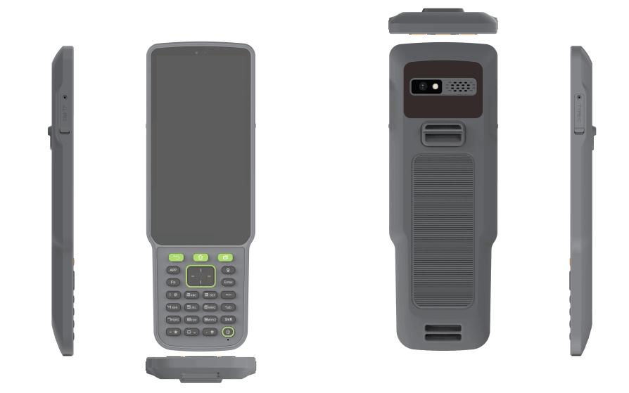
Figure 1.10 TC80 Controller
Power on: Press and hold the power button for 3 seconds
Power off: Press and hold the power button for 3 seconds, select 'Power Off' in the menu option.
Reboot: Press and hold the power button for 2 seconds and click "Restart" in the menu option.
Forced restart: Press and hold the power button for 8 seconds to force the controller to restart.
Introduction of functional keys:
-
Menu Key: Select to show applications that was used recently.
-
Home Key: Return to home screen. To view recent application, press and hold the home key.
-
Back Key: Return to previous screen.
-
APP Key: Quick start Nuwa application.
-
Positioning Key: Perform the function of starting measurement in the Survey and Stakeout interface of Nuwa application.
-
**Short Press on Power Key:**Control the screen on and off.
-
Enter Key: Execute the function of confirming in Nuwa application.
The accessories of TC80 Controller are listed below.
TC80 Charger
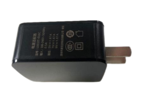
Figure 1.11 TC80 Charger
Type-C Cable
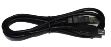
Figure 1.12 Type-C Cable
Functions:
1. Connect to the USB port of computer for data downloading;
2. Connect to the charger to charge TC80 controller.
1.3.5 Other accessories
Other accessories may be packed according to customer requirements.
The GNSS antenna connector is used to install TS21 to a tripod.
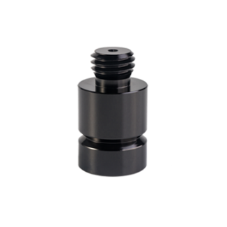
Figure 1.13 GNSS antenna connector
The height measure accessory is used to determine the height of TS21 with higher accuracy.
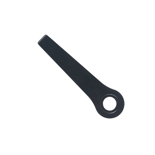
Figure 1.14 Height measure accessory
The 450-470MHz radio whip antenna is to be installed on the TNC port to transmit or receive signal for the internal radio. And 430-450MHz radio antenna, 410-430MHz radio antenna, 410-470MHz radio antenna are optional.
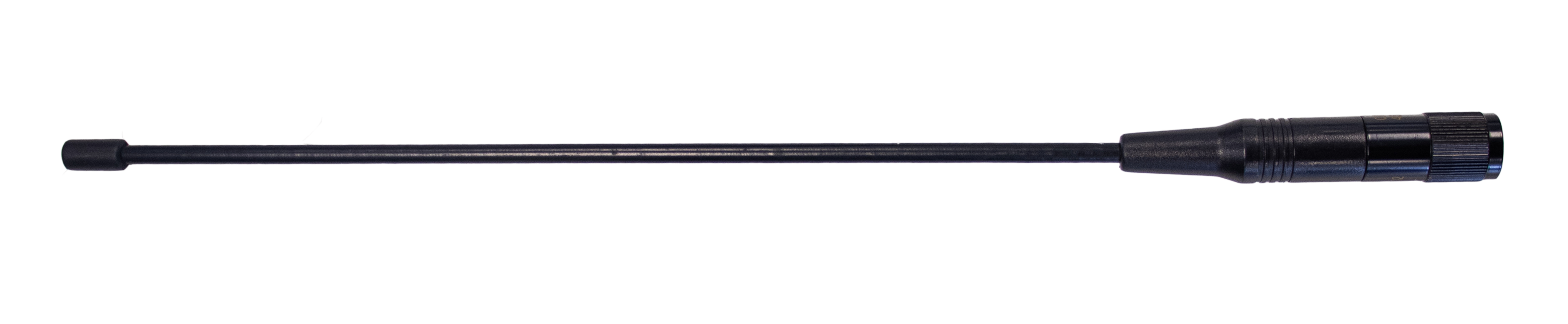
Figure 1.15 450-470MHz radio whip antenna
When using TS21 as a rover, you need a ranging pole.
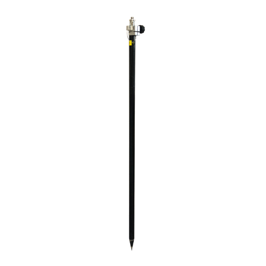
Figure 1.16 Ranging Pole
The bracket for TC80 controller is to fix the TC80 controller on a ranging pole.
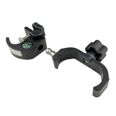
Figure 1.17 Bracket for TC80
A yellow carrying case is to store all the devices and accessories except ranging pole, high gain radio antenna and telescopic pole.

Figure 1.18 Carrying Case