Introduction
This chapter includes overview, receiver features, and devices in the package.
Overview
The Oscar GNSS receiver is a new generation GNSS RTK system. It supports calibration-free tilt compensation function which is immune to magnetic disturbances, leveling pole is not required. Easy configuration with 1.54 inch interactive screen on Ultimate and Advanced versions. With an internal high-performance multi-constellation and multi-frequency GNSS board, the Oscar GNSS receiver can provide high accuracy and stable signal detection. The high-performance antenna can speed up the time to first fix (TTFF) and improve anti-jamming performance. The built-in large capacity battery is detachable, two batteries support up to 16 hours of field work in 4G/3G/2G network and Rover radio mode. The built-in UHF radio module supports long distance communication. The rugged housing protects the equipment from harsh environments.
The Oscar GNSS receiver has three versions: Ultimate, Advanced, and Basic. It provides selectivity for the requirement from different users.
Receiver features
The Oscar GNSS receiver has following features:
- Supports multiple constellations & frequencies
<!-- -->
-
GPS L1C/A, L2C, L2P, L5
-
GLONASS L1C/A, L2C/A
-
Beidou B1, B2, B3 , support BDS-3
-
Galileo E1, E5a, E5b
-
QZSS L1C/A, L2C, L5
-
SBAS supports WAAS, EGNOS, GAGAN, SDCM, MSAS (Optional for Oscar Basic and Advanced)
<!-- -->
-
Supports 576 channels.
-
Supports 410-470MHz UHF radio, 4G network, Wi-Fi , Bluetooth, NFC.
-
Tilt compensation without calibration, immune to magnetic disturbances ^(1)^.
-
16GB/8GB internal storage
-
Up to 16 hours^(2)^ working in 4G/3G/2G network and Rover radio mode
-
IP68-rated dust- & waterproof enclosure, for reliability in harsh environmental conditions
-
Free subscription of Tersus Caster Service (TCS): transmit the correction data from Oscar Base to Rover
Note:
(1) Tilt compensation is only applicable for Ultimate version.
(2) One battery lasts up to 8 hours when Oscar works in 4G/3G/2G network and Rover radio mode. Two batteries add up to total 16 hours use.
Devices in the package
The devices in the package may vary according to the customer requirement. Here describes the major parts in the package.
Oscar GNSS receiver
The Oscar GNSS receiver has three versions which are shown as below.
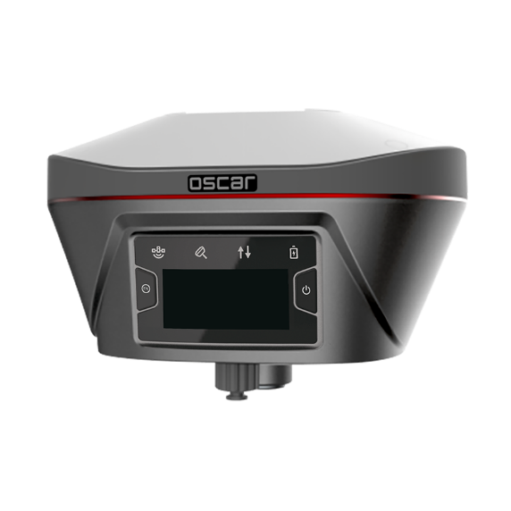
Figure 1.1[]{#_Toc29325 .anchor} Oscar GNSS receiver - Ultimate
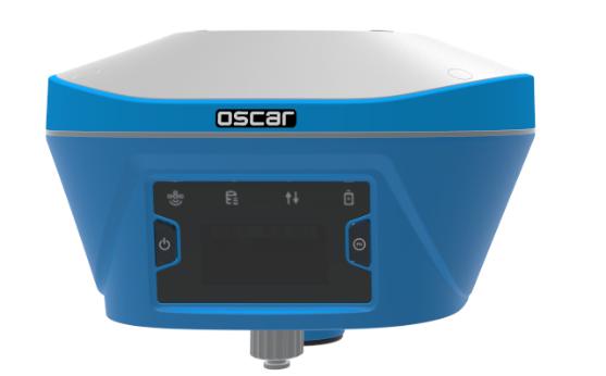
Figure 1.2[]{#_Toc30344 .anchor} Oscar GNSS receiver - Advanced

Figure 1.3[]{#_Toc10490 .anchor} Oscar GNSS receiver - Basic
**
**
Buttons
Two buttons are equipped on each version of Oscar GNSS receiver.
[![]() ]: Power ON/OFF button. When the device is off, long press it for 2 seconds to power on the receiver. When the receiver is on, long press it for over 3 seconds to power off the receiver. In addition, for Ultimate and Advanced versions, in normal operation state this button is used as function selection confirmation button working with the FN button which is explained below.
]: Power ON/OFF button. When the device is off, long press it for 2 seconds to power on the receiver. When the receiver is on, long press it for over 3 seconds to power off the receiver. In addition, for Ultimate and Advanced versions, in normal operation state this button is used as function selection confirmation button working with the FN button which is explained below.
[![]() ]: Function (FN) button. This button has different functions for different versions which is listed in the table below.
]: Function (FN) button. This button has different functions for different versions which is listed in the table below.
Table 1.1[]{#_Toc8595 .anchor} Usage of FN button for three versions
FN button Ultimate Advanced Basic
Selecting / Switching On the Device Config page, press it once to lead the cursor jump to the next row or next page or previous page. When the cursor stops at an item, pressing the power button enters the sub menu of this item for function selecting or return. Switch static survey. After pressing it for 3s to turn on the static recording function. Then press it to turn on the static mode. Press and hold it for 3s to turn off the static function.
Wake up Tap the power button or FN button to wake up the OLED screen when the OLED screen is off. N/A
Combination Function of the two buttons
Press and hold the FN button, continuously tap the ON/OFF button 5 times to reset the GNSS module and make it re-search the satellites. Detailed LED flash status related to this operation refers to the LED flash patterns table.
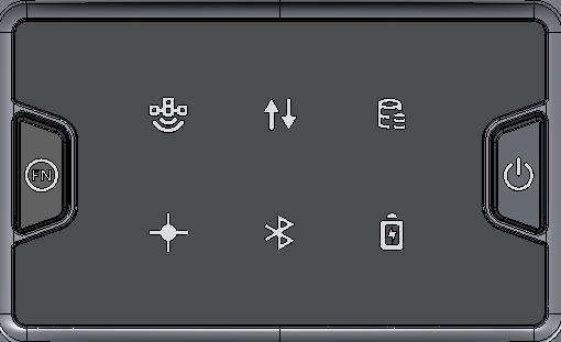
LED Indicators
Four LED indicators and one OLED display screen are for Ultimate version and Advanced version. Six LED indicators are for Basic version of Oscar GNSS receiver. The LEDs on the front panel indicate various operating conditions. The detailed LED Descriptions are shown in the tables below.
Battery
Satellite
Correction Data
Tilt Compensation
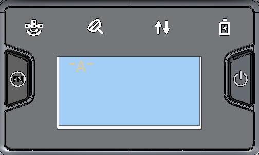
Power ON/OFF
Function
OLED display
Figure 1.4[]{#_Toc20752 .anchor} Buttons and display on Oscar Ultimate
Table 1.2[]{#_Toc9516 .anchor} LED indicators on Ultimate version
+---------------------------------------------------------------------------------------------------------------------------------------------+------------------------------------------------------------------------------------------------------------------------------------------------------------------------------------------------------+
| LED indicator | Description |
+---------------------------------------------------------------------------------------------------------------------------------------------+------------------------------------------------------------------------------------------------------------------------------------------------------------------------------------------------------+
| ![]() | Green LED. Flashing every 5 seconds indicates that it is searching satellites. After satellites are searched, it flashes N times every 5 seconds, in which N indicates N satellites are found. |
| | |
| Satellite | |
+---------------------------------------------------------------------------------------------------------------------------------------------+------------------------------------------------------------------------------------------------------------------------------------------------------------------------------------------------------+
|
| Green LED. Flashing every 5 seconds indicates that it is searching satellites. After satellites are searched, it flashes N times every 5 seconds, in which N indicates N satellites are found. |
| | |
| Satellite | |
+---------------------------------------------------------------------------------------------------------------------------------------------+------------------------------------------------------------------------------------------------------------------------------------------------------------------------------------------------------+
| ![]() | Green & Red LED. When tilt compensation is turned on, it is steady red; when it is preparing for tilt compensation, it flashes red; when tilt compensation is valid, the LED is steady green. |
| | |
| Tilt compensation | |
+---------------------------------------------------------------------------------------------------------------------------------------------+------------------------------------------------------------------------------------------------------------------------------------------------------------------------------------------------------+
|
| Green & Red LED. When tilt compensation is turned on, it is steady red; when it is preparing for tilt compensation, it flashes red; when tilt compensation is valid, the LED is steady green. |
| | |
| Tilt compensation | |
+---------------------------------------------------------------------------------------------------------------------------------------------+------------------------------------------------------------------------------------------------------------------------------------------------------------------------------------------------------+
| ![]() | Green and Red LED. Green indicates correction data, and red indicates solution status. |
| | |
| Correction data | |
+---------------------------------------------------------------------------------------------------------------------------------------------+------------------------------------------------------------------------------------------------------------------------------------------------------------------------------------------------------+
|
| Green and Red LED. Green indicates correction data, and red indicates solution status. |
| | |
| Correction data | |
+---------------------------------------------------------------------------------------------------------------------------------------------+------------------------------------------------------------------------------------------------------------------------------------------------------------------------------------------------------+
| ![]() | Green LED. Steady green in normal operation. Slow flash indicates the battery level is between 30% and 10%. Fast flash indicates the battery level is below 10% and reminds users to change battery. |
| | |
| Battery | |
+---------------------------------------------------------------------------------------------------------------------------------------------+------------------------------------------------------------------------------------------------------------------------------------------------------------------------------------------------------+
| Green LED. Steady green in normal operation. Slow flash indicates the battery level is between 30% and 10%. Fast flash indicates the battery level is below 10% and reminds users to change battery. |
| | |
| Battery | |
+---------------------------------------------------------------------------------------------------------------------------------------------+------------------------------------------------------------------------------------------------------------------------------------------------------------------------------------------------------+
Battery
Satellite
Correction Data
Static Survey
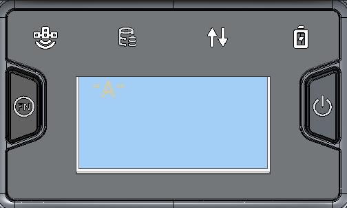
Power ON/OFF
Function
OLED display
Figure 1.5[]{#_Toc32551 .anchor} Buttons and display on Oscar Advanced
Table 1.3[]{#_Toc7509 .anchor} LED indicators on Advanced version
+---------------------------------------------------------------------------------------------------------------------------------------------+------------------------------------------------------------------------------------------------------------------------------------------------------------------------------------------------------+
| LED indicator | Description |
+---------------------------------------------------------------------------------------------------------------------------------------------+------------------------------------------------------------------------------------------------------------------------------------------------------------------------------------------------------+
| ![]() | Green LED. Flashing every 5 seconds indicates that it is searching satellites. After satellites are searched, it flashes N times every 5 seconds, in which N indicates N satellites are found. |
| | |
| Satellite | |
+---------------------------------------------------------------------------------------------------------------------------------------------+------------------------------------------------------------------------------------------------------------------------------------------------------------------------------------------------------+
|
| Green LED. Flashing every 5 seconds indicates that it is searching satellites. After satellites are searched, it flashes N times every 5 seconds, in which N indicates N satellites are found. |
| | |
| Satellite | |
+---------------------------------------------------------------------------------------------------------------------------------------------+------------------------------------------------------------------------------------------------------------------------------------------------------------------------------------------------------+
| ![]() | Green LED indicates static survey mode. |
| | |
| Static Survey | |
+---------------------------------------------------------------------------------------------------------------------------------------------+------------------------------------------------------------------------------------------------------------------------------------------------------------------------------------------------------+
|
| Green LED indicates static survey mode. |
| | |
| Static Survey | |
+---------------------------------------------------------------------------------------------------------------------------------------------+------------------------------------------------------------------------------------------------------------------------------------------------------------------------------------------------------+
| ![]() | Green and Red LED. Green indicates correction data, and red indicates solution status. |
| | |
| Correction data | |
+---------------------------------------------------------------------------------------------------------------------------------------------+------------------------------------------------------------------------------------------------------------------------------------------------------------------------------------------------------+
|
| Green and Red LED. Green indicates correction data, and red indicates solution status. |
| | |
| Correction data | |
+---------------------------------------------------------------------------------------------------------------------------------------------+------------------------------------------------------------------------------------------------------------------------------------------------------------------------------------------------------+
| ![]() | Green LED. Steady green in normal operation. Slow flash indicates the battery level is between 30% and 10%. Fast flash indicates the battery level is below 10% and reminds users to change battery. |
| | |
| Battery | |
+---------------------------------------------------------------------------------------------------------------------------------------------+------------------------------------------------------------------------------------------------------------------------------------------------------------------------------------------------------+
| Green LED. Steady green in normal operation. Slow flash indicates the battery level is between 30% and 10%. Fast flash indicates the battery level is below 10% and reminds users to change battery. |
| | |
| Battery | |
+---------------------------------------------------------------------------------------------------------------------------------------------+------------------------------------------------------------------------------------------------------------------------------------------------------------------------------------------------------+
Static Survey
Satellite
Correction Data
Solution status
Battery
Bluetooth
Power ON/OFF
Function
Figure 1.6[]{#_Toc29803 .anchor} Buttons and LEDs on Oscar Basic
Table 1.4[]{#_Toc14107 .anchor} LED indicators on Basic version
+---------------------------------------------------------------------------------------------------------------------------------------------+------------------------------------------------------------------------------------------------------------------------------------------------------------------------------------------------------+
| LED indicator | Description |
+---------------------------------------------------------------------------------------------------------------------------------------------+------------------------------------------------------------------------------------------------------------------------------------------------------------------------------------------------------+
| ![]() | Green LED. Flashing every 5 seconds indicates that it is searching satellites. After satellites are searched, it flashes N times every 5 seconds, in which N indicates N satellites are found. |
| | |
| Satellite | |
+---------------------------------------------------------------------------------------------------------------------------------------------+------------------------------------------------------------------------------------------------------------------------------------------------------------------------------------------------------+
|
| Green LED. Flashing every 5 seconds indicates that it is searching satellites. After satellites are searched, it flashes N times every 5 seconds, in which N indicates N satellites are found. |
| | |
| Satellite | |
+---------------------------------------------------------------------------------------------------------------------------------------------+------------------------------------------------------------------------------------------------------------------------------------------------------------------------------------------------------+
| ![]() | Green LED indicates correction data. |
| | |
| Correction data | |
+---------------------------------------------------------------------------------------------------------------------------------------------+------------------------------------------------------------------------------------------------------------------------------------------------------------------------------------------------------+
|
| Green LED indicates correction data. |
| | |
| Correction data | |
+---------------------------------------------------------------------------------------------------------------------------------------------+------------------------------------------------------------------------------------------------------------------------------------------------------------------------------------------------------+
| ![]() | Green LED indicates static survey mode. |
| | |
| Static Survey | |
+---------------------------------------------------------------------------------------------------------------------------------------------+------------------------------------------------------------------------------------------------------------------------------------------------------------------------------------------------------+
|
| Green LED indicates static survey mode. |
| | |
| Static Survey | |
+---------------------------------------------------------------------------------------------------------------------------------------------+------------------------------------------------------------------------------------------------------------------------------------------------------------------------------------------------------+
| ![]() | Green LED. Steady green indicates fixed solution, flashing 1Hz indicates floating solution, off light for other solutions. |
| | |
| Solution status | |
+---------------------------------------------------------------------------------------------------------------------------------------------+------------------------------------------------------------------------------------------------------------------------------------------------------------------------------------------------------+
|
| Green LED. Steady green indicates fixed solution, flashing 1Hz indicates floating solution, off light for other solutions. |
| | |
| Solution status | |
+---------------------------------------------------------------------------------------------------------------------------------------------+------------------------------------------------------------------------------------------------------------------------------------------------------------------------------------------------------+
| ![]() | Green LED indicates Bluetooth status. Steady green indicates successful Bluetooth pair, off light indicates no Bluetooth paired. |
| | |
| Bluetooth | |
+---------------------------------------------------------------------------------------------------------------------------------------------+------------------------------------------------------------------------------------------------------------------------------------------------------------------------------------------------------+
|
| Green LED indicates Bluetooth status. Steady green indicates successful Bluetooth pair, off light indicates no Bluetooth paired. |
| | |
| Bluetooth | |
+---------------------------------------------------------------------------------------------------------------------------------------------+------------------------------------------------------------------------------------------------------------------------------------------------------------------------------------------------------+
| ![]() | Green LED. Steady green in normal operation. Slow flash indicates the battery level is between 30% and 10%. Fast flash indicates the battery level is below 10% and reminds users to change battery. |
| | |
| Battery | |
+---------------------------------------------------------------------------------------------------------------------------------------------+------------------------------------------------------------------------------------------------------------------------------------------------------------------------------------------------------+
| Green LED. Steady green in normal operation. Slow flash indicates the battery level is between 30% and 10%. Fast flash indicates the battery level is below 10% and reminds users to change battery. |
| | |
| Battery | |
+---------------------------------------------------------------------------------------------------------------------------------------------+------------------------------------------------------------------------------------------------------------------------------------------------------------------------------------------------------+
LED Flash Patterns
The possible flash patterns of various states of receiver operation are listed in the table below.
Table 1.5[]{#_Toc8352 .anchor} Possible LED flash patterns
Receiver mode Button operation LED flash patterns
Receiver OFF N/A All LEDs are off.
Receiver ON Long press the power button for 2s All LEDs are on, then all off, and each LED starts to indicate current status after initialization.
Low power N/A Battery LED flashes slow.
Battery exhausting N/A Battery LED flashes fast.
Searching satellites N/A Satellite LED flashes every 5s
Satellites tracked N/A Satellite LED flashes N times every 5s, in which N is the quantity of satellites tracked.
Receiving valid data packet N/A Correction data LED flashes green at 1Hz
Fixed solution N/A Correction data LED is steady red for Ultimate and Advanced versions, Solution status LED is steady green for Basic version.
Floating solution N/A Correction data LED flashes red at 1Hz for Ultimate and Advanced versions, Solution status LED flashes green at 1Hz for Basic version.
Reset GNSS module Press and hold the FN button, continuously tap the ON/OFF button 5 times All LEDs light up for 5 seconds.
Turn on static mode Press FN button for 3s Static/Tilt LED flashes 3 times continuously.
Turn off static mode Press FN button for 3s The correction data LED flashes 3 times continuously.
Firmware upgrade N/A For Basic version, all six LEDs are on for 1s thereafter only power LED lights up, then all LEDs light up when upgrading, lights off when restarting. Then all six LEDs light up for 1s thereafter only power LED lights up means it restarts successfully with updated firmware.
Note: N/A means Not Applicable.
**
**
Receiver Ports
The bottom of Oscar receiver is shown as below.
Serial port & external power
Mini USB port
TNC port
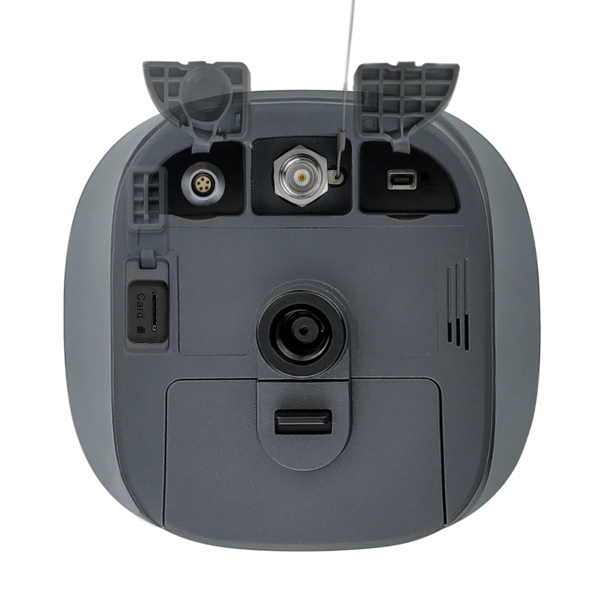
SIM slot
Battery compartment
Screw hole
Speaker
Figure 1.7[]{#_Toc14442 .anchor} Bottom of Oscar GNSS receiver
Table 1.6[]{#_Toc30429 .anchor} Receiver ports on the bottom side
Icon Connector Name Connections
![]()
![]() Serial port & external power External power, RS-232 communication, external radio
Serial port & external power External power, RS-232 communication, external radio
![]()
![]() Mini USB port Device, computer, USB drive
Mini USB port Device, computer, USB drive
SIM  SIM slot Nano SIM card
-  TNC port 410-470MHz radio antenna
-  Screw hole 5/8'' x 11 UNC-2B connector for corresponding connector and pole.
Battery and charger
Oscar equips smart lithium batteries which can detect electricity and display the power level intelligently. The Oscar GNSS receiver can also be powered by external power source via serial data port. The built-in large capacity battery is detachable, two batteries support up to 16 hours of field work in 4G/3G/2G mode and rover radio mode.
The BN20 battery is shown as below. Press the button on the top, it shows the power level left to be consumed.
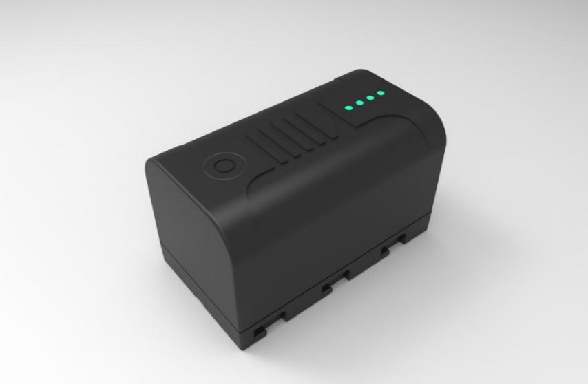
Figure 1.8[]{#_Toc21573 .anchor} BN20 Battery
The CN20 Charger is able to charge two BN20 batteries at the same time which is shown in the figures below.
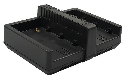
Figure 1.9[]{#_Toc10340 .anchor} CN20 Charger
Place two BN20 batteries in the slots of CN20 charger.
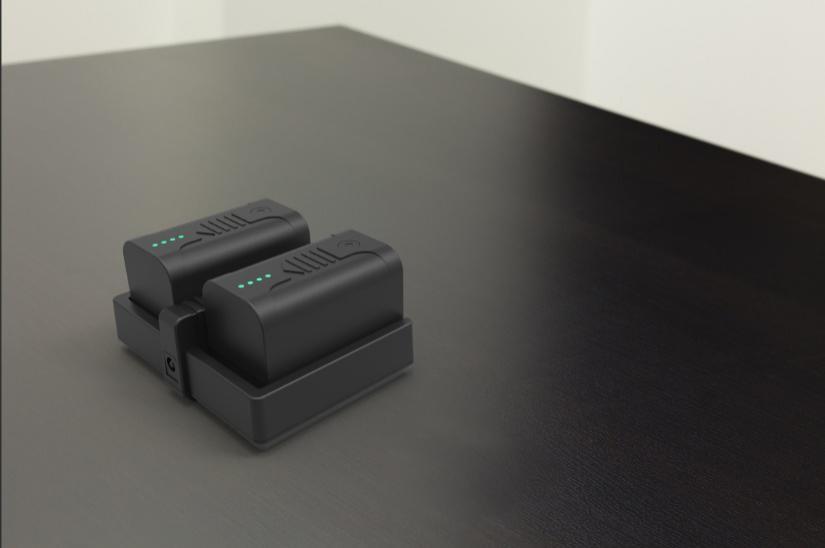
Figure 1.10[]{#_Toc14556 .anchor} CN20 Charger with two BN20 batteries
Insert the DC Jack connector of the adapter to the CN20 charger, then make the adapter with cable plug in the local AC outlet (100~240V AC) to start charging.
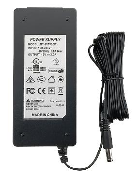
Figure 1.11[]{#_Toc28130 .anchor} CN20 Charger Adapter
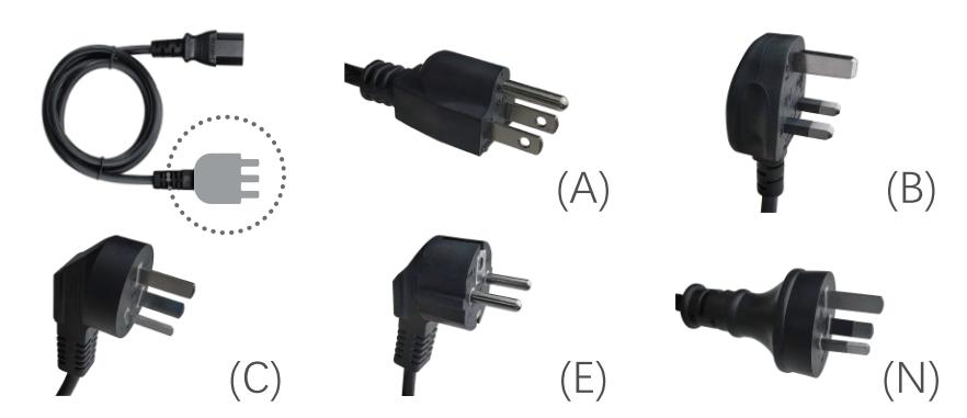
Figure 1.12[]{#_Toc28932 .anchor} CN20 Charger Adapter Cable (A/B/C/E/N)
Note: The model of the CN20 charger adapter cable will be delivered according to customer requirements.
A: American, B: British, C: Chinese, E: European, N: Australian
Charge the battery completely before using it for the first time. The charging takes approximately 3 hours per battery at room temperature. If the battery has been stored for longer than three months, charge it before use.
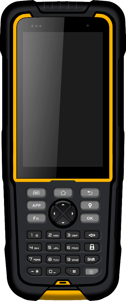
TC20 controller
The Tersus TC20 Controller is a rugged android smart phone with design of 4.3'' touch screen and an alphanumerical keypad. Equipped with powerful processor, it is perfect to adapt with Tersus Survey software. With professional IP68 rating, it is robust and reliable for harsh operating conditions.
Features:
-
Rugged smart phone 4.3'' display
-
4G GSM unlocked Android 6.0
-
Quad-Core 1.3GHz CPU
-
2GB RAM + 16GB ROM
-
8 MP Auto Focus camera
-
IP68 certified grade, water/shock/dust proof
-
6500 mAh battery
-
Wi-Fi, Bluetooth, NFC
-
Two color options: red and yellow
Note: Although the TC20 controller uses chemical and impact resistant materials, precision instruments require careful use and maintenance and should be kept as dry as possible. In order to improve the stability and life cycle of the TC20 controller, avoid exposing the TC20 controller to extreme environments such as moisture, high temperatures, low temperatures, corrosive liquids or gases.
TC20 must be in the specified temperature range -20 °C \~ 55 °C when used and stored.
Power on: Press and hold the power button for 3 seconds. Short press to wake up the screen.
Power off: Press and hold the power button for 3 seconds, select 'power off' in the menu option.
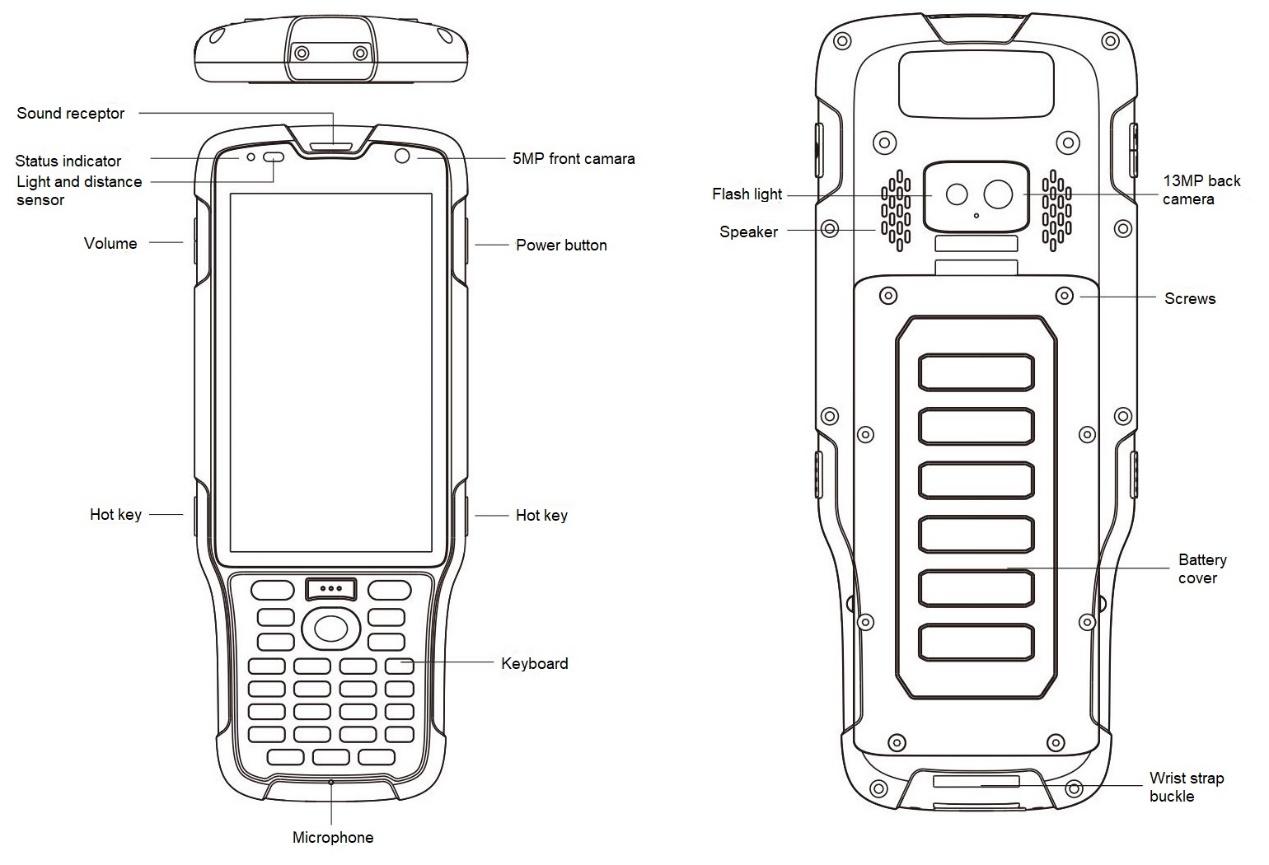
Flash器、、、、、、、
Speaker
Rear camera
Rear camera
Rear cameraRear camera
Rear camera器、、、、、、、
USB/Earphone Jack
Light sensors
LED indicator light


Physical keyboard
NFC
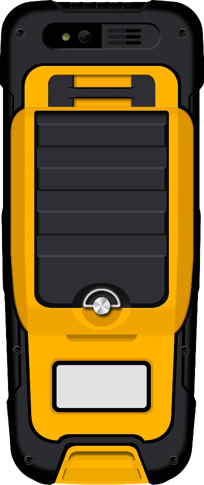
Figure 1.13 Four sides of TC20 controller
Menu key: Select to show the available menu in current screen.
Home key: Return to home screen. Press and hold it to view recent application.
Back key: Return to previous screen.
APP key: launch Nuwa app.
Point key: collect point manually under survey interface.
FN key: shift keypad language under some input method.
OK key: confirm or wrap to the next line.
Accessories of TC20 controller:
TC20 lithium battery (3.7V/6500mAh)
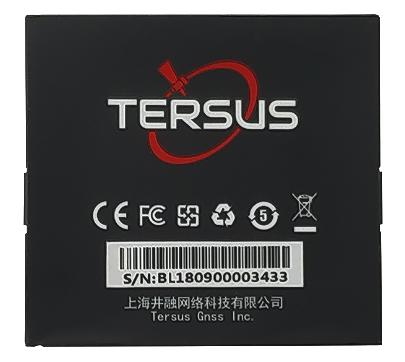
Figure 1.14[]{#_Toc21761 .anchor} TC20 lithium battery
TC20 charger adapter (5V/1A) with one USB port
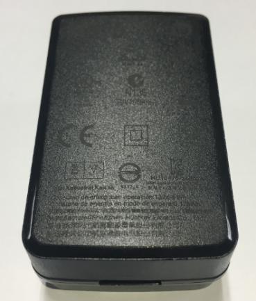
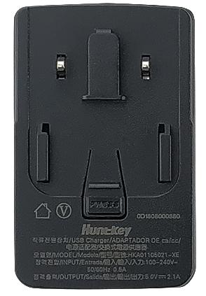
Figure 1.15[]{#_Toc25967 .anchor} TC20 charger adapter
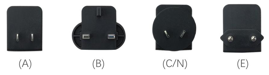
Figure 1.16[]{#_Toc9366 .anchor} TC20 charger adapter plugs
A: American, B: British, C: Chinese, E: European, N: Australian
Put the plug in in the back of the adapter to assemble the TC20 charger.
The hand strap below is for easy handling of TC20 controller.

Figure 1.17[]{#_Toc28971 .anchor} TC20 controller hand strap
The stylus pen below is for easy touch of screen on TC20 controller.

Figure 1.18[]{#_Toc23244 .anchor} Stylus pen for TC20
TC50 controller
The Tersus TC50 Controller is a rugged multi-functional data controller with design of 5 inch sunlight readable HD touch screen and an alphanumerical keypad. Equipped with powerful processor and android operating system, it is perfect to adapt with Tersus survey software. With professional IP68 rating, it is robust and reliable for harsh operating conditions. The large capacity lithium battery guarantees more than 10 hours of field working for a whole day of multiple surveying tasks.
Features:
-
5 inch sunlight readable HD touch screen
-
Octa-core 2.0GHz CPU
-
Android 8.1 operating system
-
4GB RAM + 64GB ROM
-
5MP front camera and 13MP rear camera
-
IP68 certified grade, water/shock/dust proof
-
7000mAh battery
-
Wi-Fi, Bluetooth, NFC, 4G
-
USB Type-C
Note: Although the TC50 controller uses chemical and impact resistant materials, precision instruments require careful use and maintenance and should be kept as dry as possible. In order to improve the stability and life cycle of the TC50 controller, avoid exposing the TC50 controller to extreme environments such as moisture, high temperatures, low temperatures, corrosive liquids or gases.
TC50 must be in the specified temperature range -20 °C \~ 55 °C when used and stored.
Power on: Press and hold the power button for 3 seconds
Power off: Press and hold the power button for 3 seconds, select 'Power Off' in the menu option.
Reboot: Press and hold the power button for 2 seconds and click "Restart" in the menu option.
Forced restart: Press and hold the power button for 8 seconds to force the controller to restart.
Introduction of functional keys:
-
Menu Key: Select to show applications that was used recently.
-
Home Key: Return to home screen. To view recent application, press and hold the home key.
-
Back Key: Return to previous screen.
-
APP Key: Quick start Nuwa application.
-
Blue Positioning
 Key: Perform the function of starting measurement in the Survey and Stakeout interface of Nuwa application.
 -
Yellow Bulb **Key:**Control the screen on and off.
ENTER Key: Execute the function of confirming in Nuwa application.
The accessories of TC50 Controller are listed below.
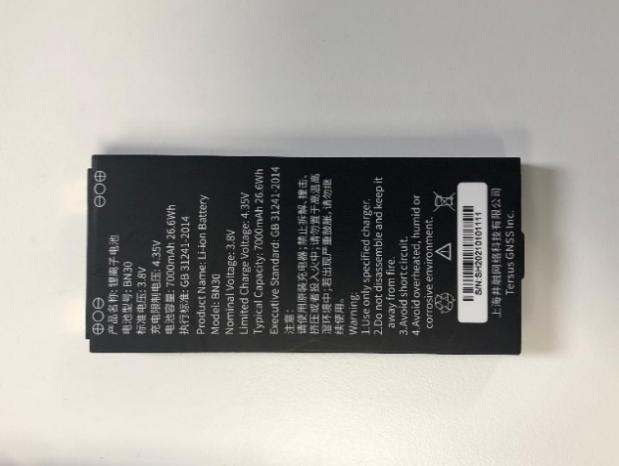
TC50 Lithium Battery (3.8V/7000mAh)
TC50 Charger (5V/1.67A, 7V/1.67A, 9V/1.67A)

Type-C Cable

Functions:
1. Connect to the USB port of computer for data downloading;
2. Connect to the charger to charge TC50 controller.
External radio for Oscar
The external radio RS400H3 for Oscar below is to be installed via serial data port, and it can help Oscar transmitting signals farther than internal radio.
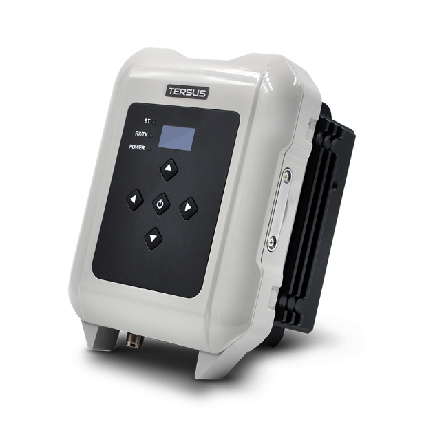
Figure 1.19[]{#_Toc9068 .anchor} External radio for Oscar
When using external radio for Oscar as a base, a high gain radio antenna and a telescopic pole are needed which are shown as below.
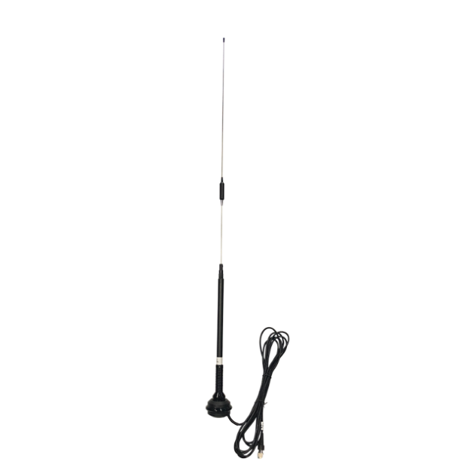
Figure 1.20[]{#_Toc7439 .anchor} High gain radio antenna
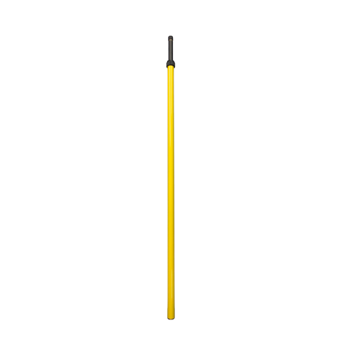
Figure 1.21[]{#_Toc20108 .anchor} Telescopic pole for radio antenna
The following Serial-5pin to External-Radio-DC-5pin & Bullet-DC Cable and Bullet-DC to Alligator Clips are used to communicate with Oscar and connect to external power supply.
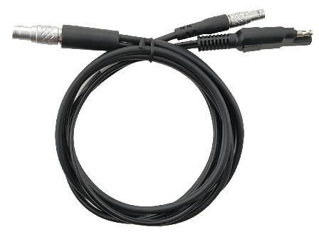
Figure 1.22[]{#_Toc24361 .anchor} Serial-5pin to External-Radio-DC-5pin & Bullet-DC Cable
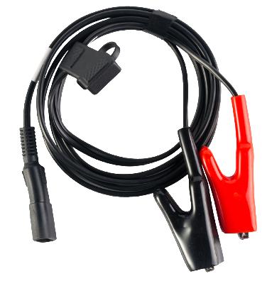
Figure 1.23[]{#_Toc2128 .anchor} Bullet-DC to Alligator Clips
Other accessories
Other accessories may be packed according to customer requirements.
The GNSS antenna connector is used to install Oscar to a tripod.
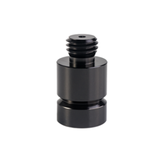
Figure 1.24[]{#_Toc26462 .anchor} GNSS antenna connector
The height measure accessory is used to determine the height of Oscar with higher accuracy.

Figure 1.25[]{#_Toc27516 .anchor} Height measure accessory
The tape measure below is to help measure height.
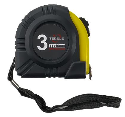
Figure 1.26[]{#_Toc23492 .anchor} Tape measure
The 410-470MHz radio whip antenna is to be installed on the TNC port to transmit or receive signal for the internal radio.
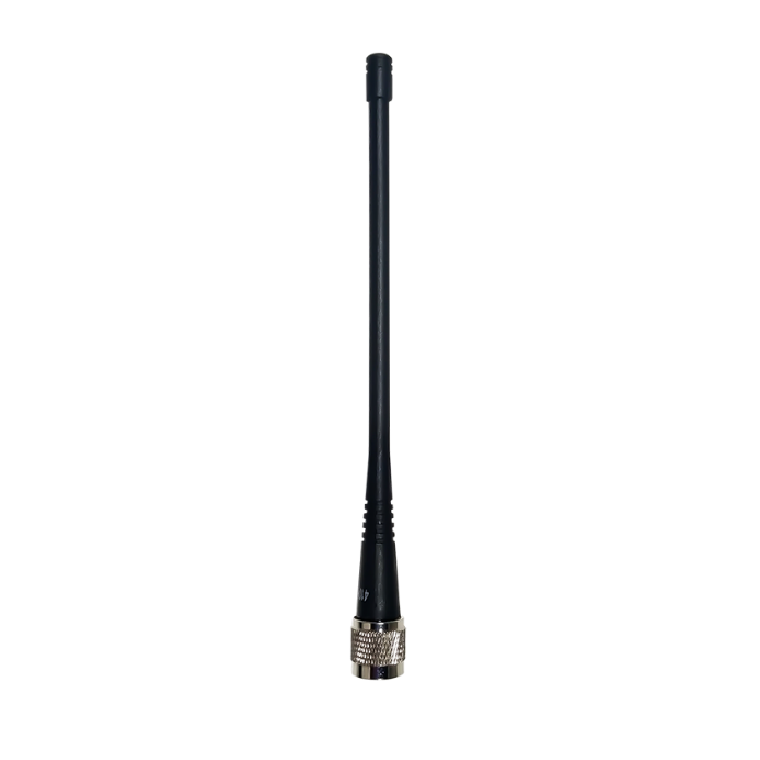
Figure 1.27[]{#_Toc20472 .anchor} 410-470MHz radio whip antenna
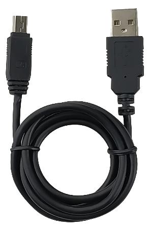
Figure 1.28[]{#_Toc13660 .anchor} Mini USB cable
Mini USB cable functions:
1. Connect Oscar to the USB port of computer for data downloading;
2. Connect the mini USB port of TC20 to charge TC20 controller.
When upgrading firmware with a wire, you need a Mini-USB OTG cable. The detailed usage refers to section 2.4.1.

Figure 1.29[]{#_Toc22121 .anchor} Mini-USB OTG cable
When installing 410-470MHz radio whip antenna on Oscar, it is necessary to use a 30cm extension pole to heighten Oscar and avoid bending the 410-470MHz radio whip antenna.
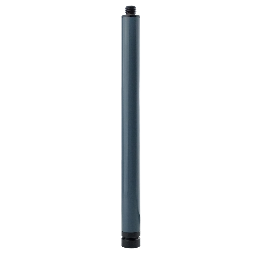
Figure 1.30[]{#_Toc32015 .anchor} Extension pole 30cm
This metal fixing plate is used to fixate the high gain radio antenna to the tripod.

Figure 1.31[]{#_Toc27665 .anchor} Metal fixing plate
When using Oscar as a rover, you need a ranging pole.
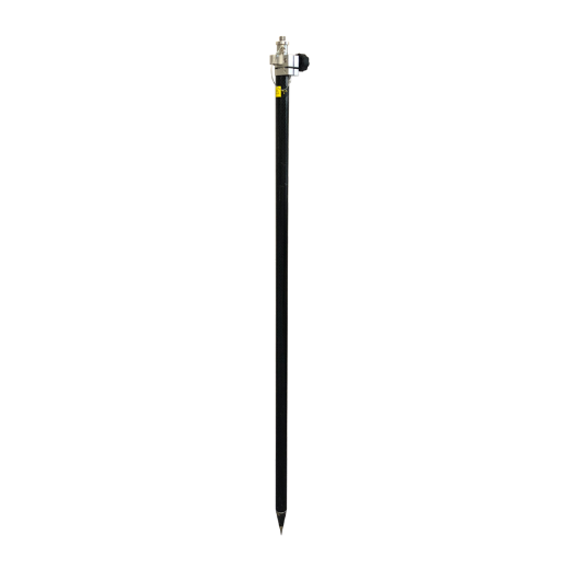
Figure 1.32[]{#_Toc4164 .anchor} Ranging Pole
The bracket for TC20 controller is to fix the TC20 controller on a ranging pole.
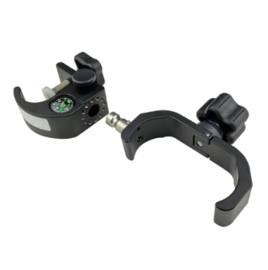
Figure 1.33[]{#_Toc4274 .anchor} Bracket for TC20
A yellow carrying case is to store all the devices and accessories except ranging pole, high gain radio antenna and telescopic pole.
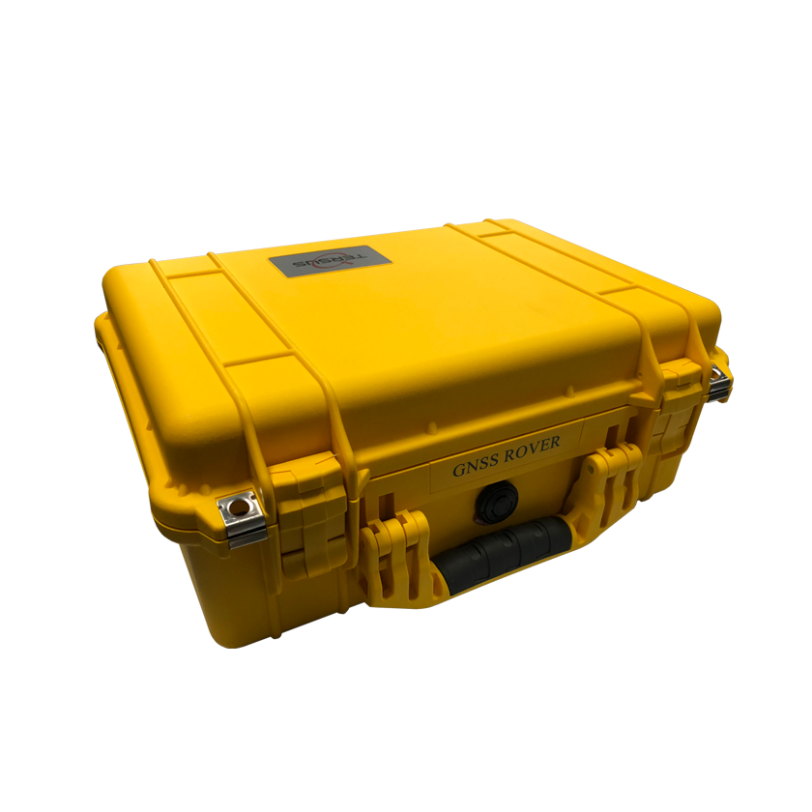
Figure 1.34[]{#_Toc23798 .anchor} Carrying Case
The tool bag below is to store high gain radio antenna and telescopic pole for radio antenna.

Figure 1.35[]{#_Toc4934 .anchor} Tool bag
The Serial-5pin to DC JACK & DB9 Male cable and the DC JACK male with two wires (the brown wire connects to power and the blue wire connects to ground) below are optional. It is to power Oscar using external power source instead of the BN20 battery.
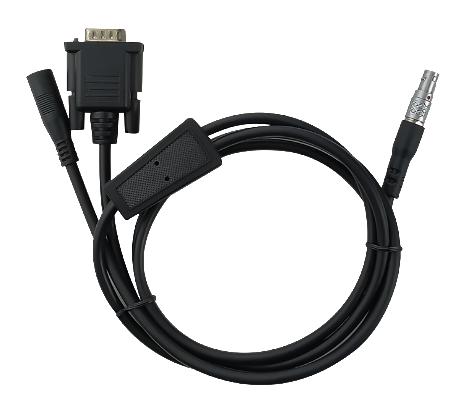
Figure 1.36[]{#_Toc9225 .anchor} Serial-5pin to DC JACK & DB9 male cable
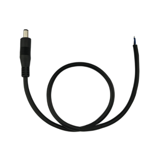
Figure 1.37[]{#_Toc1775 .anchor} DC JACK male with two wires
The DB9 Female to USB Type A Male converter cable is to convert DB9 male to USB Type A male connector, so that it can connect to the USB port of a computer.
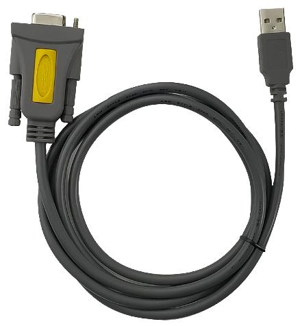
Figure 1.38[]{#_Toc13790 .anchor} DB9 Female to USB Type A Male converter cable
The configuration cable for 25W radio below is used to configure parameters of the 25W radio instead of the default setting.
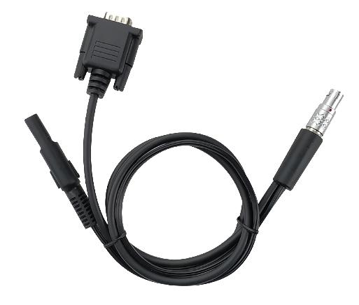
Figure 1.39[]{#_Toc1073 .anchor} Configuration cable for 25W radio