Visual Positioning
5.1 Introduction
Visual Positioning for Tersus Trek GNSS Receiver is an innovative integration of GNSS, IMU and visual positioning technology. Equipped with a global shutter camera, the Trek not only captures the coordinates of points of interest from recorded video but also generates point cloud data on-site in real time.
5.2 Connect and Take Video
1) Connect Trek via WiFi and start rover mode to get a fixed solution.
2) Turn on Tilt, input the correct pole height and finish the tilt initialization.
3) Go to [Survey] - [Visual Positioning]. The main interface shows Trek camera shooting screen. When the upper-right precision estimate is too large and the icon shows red, shake the pole or move Trek according to the animation shown to take tilt initialization and visual positioning initialization until the upper-right precision estimate meets the requirements, the icon shows green and the animation disappears.
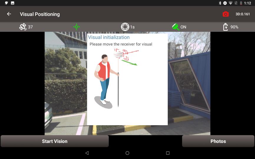
Figure 5.1 Visual Positioning Initialization
4) Click [Start Vision], keep the camera on Trek facing the target points, move Trek to take photos of the target points from different directions.
5) Click [Stop] to end recording. Check the quality and the number of pictures for this visual positioning and enter the group name..
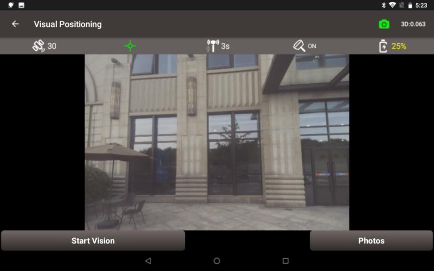
Figure 5.2 Start Vision
Note:
-
Ensure that the Trek is located in an open sky environment, without any obstruction to the GNSS antenna, throughout the initialization process.
-
Remember not to rotate the receiver violently during the initialization process. To improve visual measurement performance, focus on ensuring sufficient moving, as rotation does not enhance it.
-
During the initialization phase, the camera should be turned back toward the surveyor to avoid obstruction of the view by their body.
-
In the moving stage, the camera should not be pointed at non-textured objects, such as the sky and white walls.
-
3D values in the upper right corner indicates the predicted 3D measuring error at 10 meter distance.
5.3 Photo Groups
Click [Photos] to view all groups of photos taken for further measurement. Click on the mode button on the upper right corner in photos screen, there are four modes to take measurement for visual positioning.
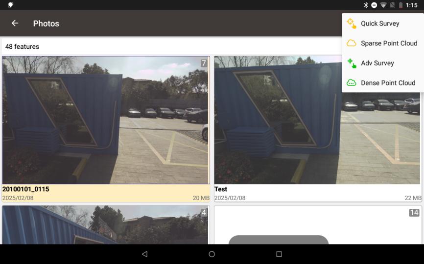
Figure 5.3 Four Measurement Modes
If needed, click the [Multi-select] button and choose the photo group to export. Then connect the Trek to a computer and locate the exported image group in the directory for 3D modeling post-processing.
5.4 Quick Survey
This section introduces Quick Survey mode. Quick Survey use the traditional Pick point - Calculate - Adjust process. Calculations are performed at the receiver side. The advantage of quick survey is that there are no controller performance requirements and calculations are faster.
1) Click on a photo group to slide through all the photos in the group.
2) Click on one of the photos that contains target points to enter the photo measurement interface. Click the target point directly on the picture, then the clicked position will show a blue cross, and you can change the position of the blue cross by dragging. You can also zoom in and out of the picture to make it easier to align the blue cross to the target point.
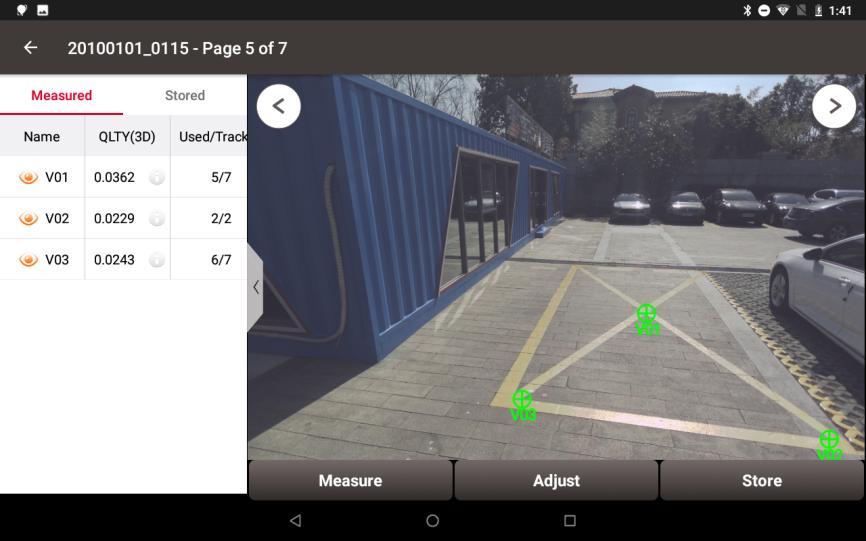
Figure 5.4 Quick Survey
3) Click [Measure], the blue cross will turn green, and the measured point list will show 3D quality and the number of used photos. Continue to select other target points in this way.
4) Switch to other photos, check whether the green cross is aligned with the target point. If failed to match on some photos, it will be shown as a red circle.
5) Click [Adjust], select the point and drag to align target manually. It will be recalculated and generally the quality will become higher and the used photos will increase.
6) Confirm that all points are measured correctly. Click the white icon ![]() to check the detailed information and edit point name. Then click [Store] and enter points information to store visual positioning points into the point database.
to check the detailed information and edit point name. Then click [Store] and enter points information to store visual positioning points into the point database.
Note:
-
Hold the receiver steady and keep a normal walking speed while capturing images.
-
For optimal accuracy and performance, capture the object of interest from a distance between 2m and 10m.
-
Avoid using it in dark conditions or when directly facing the sun, as it may lead to difficulty in recognizing enough features in the captured images to make a match.
-
Try to select feature points on an image directly in front of the target object. For example, choose an image in the middle of the captured images.
-
Multiple feature points can be selected at a time.
5.5 Sparse Point Cloud
This section introduces Sparse Point Cloud mode. In this mode, you need to circle the position around the target point first, then after the sparse point cloud being generated, select the nearest point in the sparse point cloud to obtain coordinates directly.
Calculations are performed at the receiver side. The advantage of this mode is that there are no controller performance requirements and calculations are faster, while at the same time the operations are simpler without adjustments.
1) Click on a photo group and click on one of the photos that contains target points. Click the circle button ![]() and draw a circle containing the target point.
and draw a circle containing the target point.
2) After the calculation, the sparse point cloud of the circled position will be displayed on the picture. If the points in the sparse point cloud are too far away from the target, draw another circle near the target position to generate more point clouds.
3) Click the select button  and click one of the point in sparse point cloud to select. If a wrong point is selected, use the button to cancel the selection.
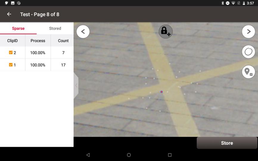
Figure 5.5 Sparse Point Cloud
4) Continue to select other target points in the way above. Then click [Store] and enter points information to store visual positioning points into the point database
5.6 Adv Survey
This section introduces Adv Survey mode. In Advanced Survey mode, the software will prepare the dense point cloud automatically first. The user only need to pick the point on the picture and the software will automatically generate the dense point cloud around the target, select the corresponding point in point cloud and give the results directly.
Calculations are performed at the controller side and therefore has performance requirements for the controller. The advantage of this mode is that the point cloud is dense and accurate, simplest for the user to operate and very accurate in measurement.
1) Click on a photo group and click on one of the photos that contains target points. It may take some time to prepare dense point cloud.
2) Click the target point directly on the picture, then the clicked position will show a blue cross, and you can change the position of the blue cross by dragging. You can also zoom in and out of the picture to make it easier to align the blue cross to the target point.
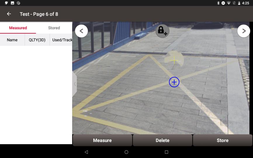
Figure 5.6 Advanced Survey
3) Click [Measure], and it may take some time to calculate the dense point cloud. The blue cross will turn green after the calculation. Select other target points in the same way.
4) Click the white icon ![]() to check the detailed information and edit point name. Click [Store] to store visual positioning points into the point database.
to check the detailed information and edit point name. Click [Store] to store visual positioning points into the point database.
5.7 Dense Point Cloud
This section introduces Dense Point Cloud mode. The measurement process in this mode is similar to that of the sparse point cloud. More importantly, we can export the dense point cloud.
Calculations are performed at the controller side and therefore has performance requirements for the controller.
-
Click on a photo group and click on one of the photos that contains target points. It may take some time to prepare dense point cloud.
2) Click the button
 and wait for global 3D point cloud reconstruction results the dense point cloud of the circled position will be displayed on the picture.
3) Click [Export] and select the path to the las file. Then open las file to check the dense point cloud generated by Trek visual positioning on site.
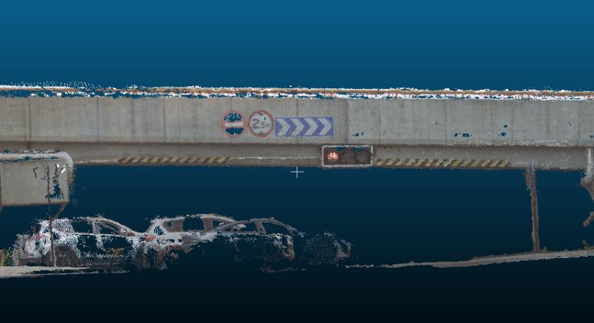
Figure 5.7 Export Dense Point Clouds