Typical Applications
This chapter introduces typical applications of LUKA GNSS receiver, and solutions for some possible issues.
Install the radio antenna before switching the radio transceiver to transmit mode, or the radio transceiver may be damaged due to overheating. The energy to be transmitted cannot be emitted out without the antenna, which may cause the temperature rise and overheat of the radio module.
4.1 Base station operation
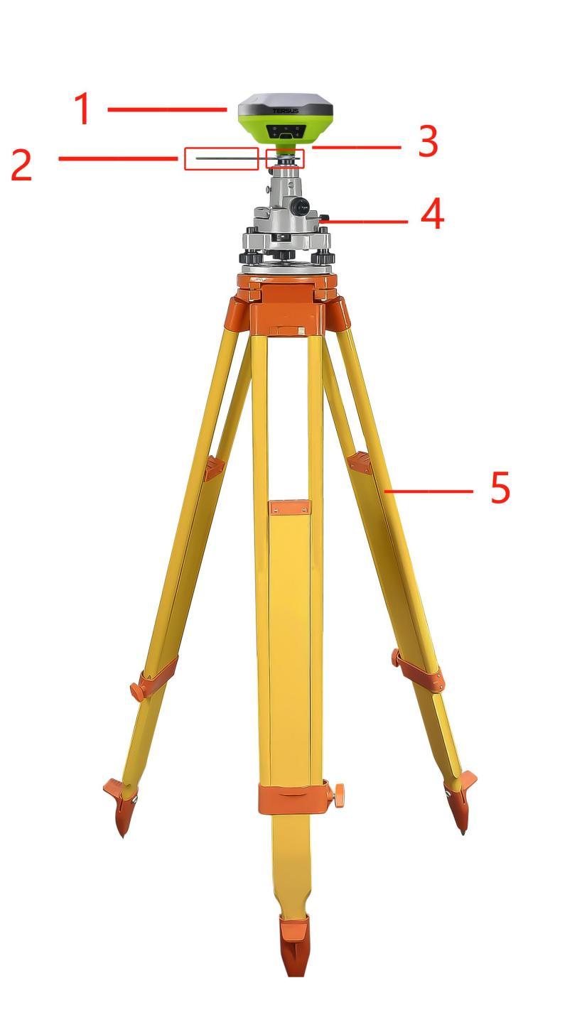
Figure 4.1[]{#_Toc16977 .anchor} LUKA as a base - network mode
Table 4.1[]{#_Toc14542 .anchor} Devices of LUKA as a base network mode
NO. Device Name
1 LUKA GNSS receiver
2 Height measure accessory
3 GNSS antenna connector
4 Tribrach
5 Tripod
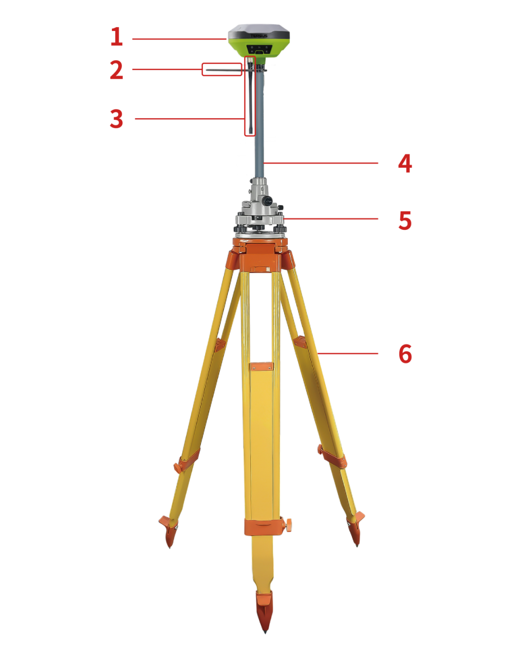
Figure 4.2[]{#_Toc11641 .anchor} LUKA as a base - internal radio
Table 4.2[]{#_Toc12694 .anchor} Devices of LUKA as a base internal radio mode
NO. Device Name
1 LUKA GNSS receiver
2 Height measure accessory
3 410-470MHz radio whip antenna
4 Extension pole 30cm
5 Tribrach
6 Tripod
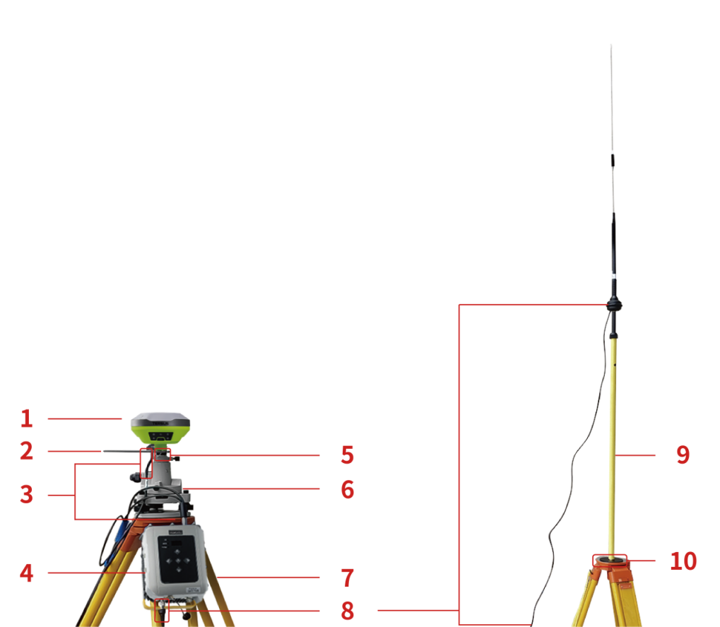
Figure 4.3[]{#_Toc21313 .anchor} LUKA as a base - external radio
Table 4.3[]{#_Toc4368 .anchor} Devices of LUKA as a base external radio mode
NO. Device Name
1 LUKA GNSS receiver
2 Height measure accessory
3 Type-C to External-Radio-DC-5pin & Bullet-DC
4 External Radio RS400H3
5 GNSS antenna connector
6 Tribrach
7 Tripod
8 High Gain Radio Antenna
9 Telescopic pole for radio antenna
10 Metal plate for radio antenna
Note: Bullet-DC connects to 'Bullet-DC to Alligator Clips', and then clip to the external power supply with 12V output.
Detailed steps of software operation:
-
Set up LUKA according section 2.1 Setting up LUKA after all the components above are ready, ensure the battery has sufficient power and insert one SIM card when 4G/3G/2G network is required for operation;
-
Long press power button to power on LUKA;
-
Use NFC function to launch Nuwa app. While the screen of TC50 Controller is unlocked, put TC50 Controller close to the LUKA NFC logo. The Bluetooth pairs automatically after a beep and Nuwa is launched requesting to open the latest project. Click [OK] and start configuring LUKA from step 7. Also you can click [Cancel] to create a new project or open an existing project, and then start configuring LUKA from step 7.
-
If using an android device without NFC function, ensure LUKA is powered on, and launch Nuwa application on the android device. Click [Project] in the main interface to create a new project or open an existing project and connect LUKA manually.
-
Back to the main interface of Nuwa app, click [Device] -> [Connect] under an opened project.
-
Select [LUKA] for the Device Type, select [Bluetooth] for the Connect Type, click [Connect Config] to search and pair the Bluetooth address of LUKA, select [LUKA] for the Antenna and click [Connect] to enable communication between the android controller and LUKA.
-
Back to [Device] - > [Base], click [New] to create a new configuration for base.
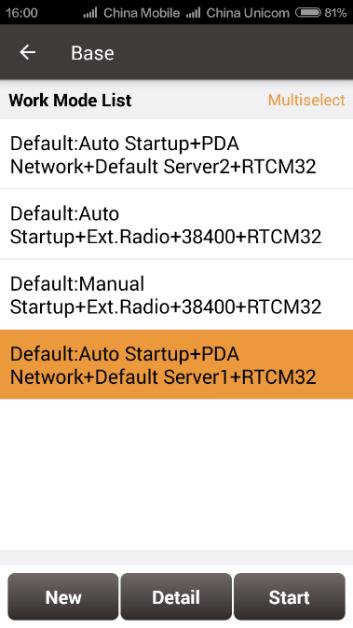
Figure 4.4[]{#_Toc17469 .anchor} Base setting interface
- Edit the base configuration for LUKA GNSS receiver. The startup mode can be chosen from auto start and manual start. If you choose manual start the base, you can manually type the base coordinate, or click the location icon to obtain the current base coordinate, or select a point from the control point library. The data link has four options: Receiver Network, PDA Network, Internal Radio and External Radio. Both the Receiver Network and PDA Network have three protocol options: Tersus Caster Service (TCS), Ntrip and TCP.
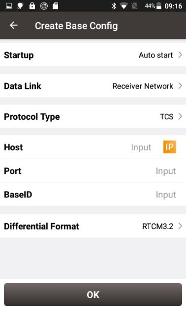
Figure 4.5[]{#_Toc30267 .anchor} Base configuration - Receiver Network (TCS)
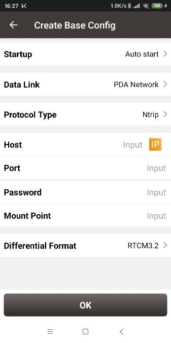
Figure 4.6[]{#_Toc4766 .anchor} Base configuration -- PDA Network (Ntrip)
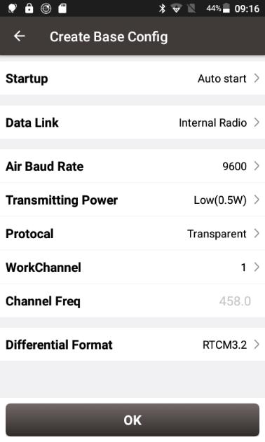 Figure 4.7[]{#_Toc23735 .anchor} Base configuration - Internal Radio
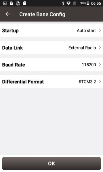 Figure 4.8[]{#_Toc6114 .anchor} Base configuration - External Radio
- After filling the information for the above configuration, click [OK]. Select this configuration in the work mode list and click [Start] to start data transmission for base which is shown as below.
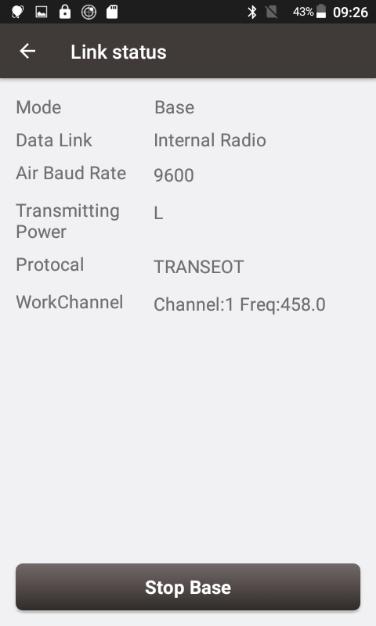
Figure 4.9[]{#_Toc21348 .anchor} Link status of base using internal radio
4.2 Rover operation
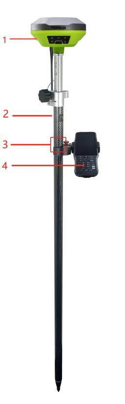
Figure 4.10[]{#_Toc29280 .anchor} LUKA as a Rover - Network Mode
Table 4.4[]{#_Toc19754 .anchor} Devices of LUKA as a rover network mode
NO. Device Name
1 LUKA GNSS receiver
2 Ranging pole
3 Bracket for TC50
4 TC50 Controller
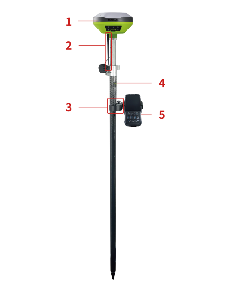
Figure 4.11[]{#_Toc14434 .anchor} LUKA as a Rover - Internal Radio
Table 4.5[]{#_Toc29083 .anchor} Devices of LUKA as a rover internal radio mode
NO. Device Name
1 LUKA GNSS receiver
2 410-470MHz radio whip antenna
3 Bracket for TC50
4 Ranging pole
5 TC50 Controller
Detailed steps of software operation:
-
Set up LUKA according section 2.1 Setting up LUKA after all the components above are ready, ensure the battery has sufficient power and insert one SIM card when 4G/3G/2G network is required for operation;
-
Long press the power button to power on LUKA;
-
Use NFC function to launch Nuwa app. While the screen of TC50 Controller is unlocked, put TC50 Controller close to the LUKA NFC logo. The Bluetooth pairs automatically after a beep and Nuwa is launched requesting to open the latest project. Click [OK] and start configuring LUKA from step 7. Also you can click [Cancel] to create a new project or open an existing project, and then start configuring LUKA from step 7.
-
If using an android device without NFC function, ensure LUKA is powered on, and launch Nuwa application on the android device. Click [Project] in the main interface to create a new project or open an existing project and connect LUKA manually.
-
Back to the main interface of Nuwa app, click [Device] -> [Connect] under an opened project;
-
Select [LUKA] for the Device Type, select [Bluetooth] for the Connect Type, click [Connect Config] to search and pair the Bluetooth address of LUKA, select [LUKA] for the Antenna and click [Connect] to enable communication between the android controller and LUKA.
-
Back to [Device] - > [Rover], click [New] to create a new configuration for base.
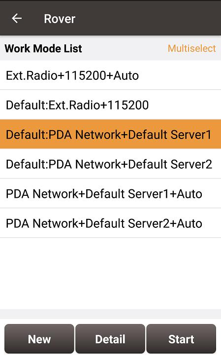
Figure 4.12[]{#_Toc10062 .anchor} Rover setting interface
- Edit rover configuration for LUKA GNSS receiver under different data link selections. The Receiver Network and PDA Network have three protocol options respectively: Ntrip, TCP and Tersus Caster Service (TCS).
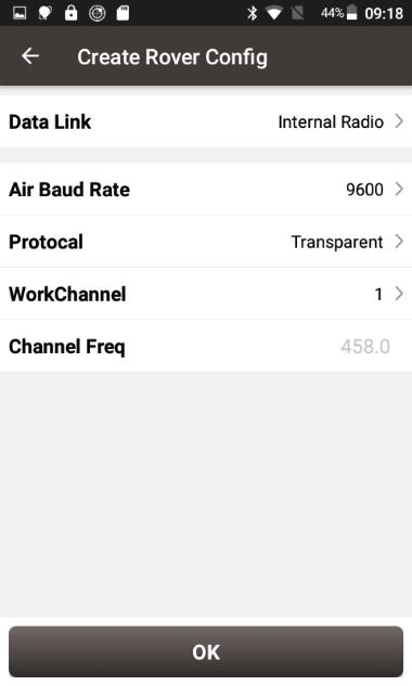
Figure 4.13[]{#_Toc7483 .anchor} Rover configuration - Internal Radio
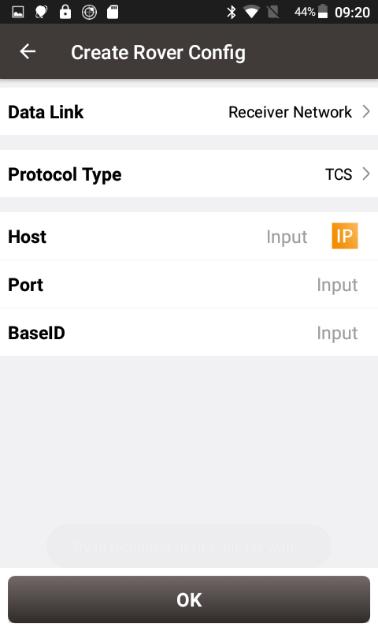
Figure 4.14[]{#_Toc32735 .anchor} Rover configuration - Receiver Network (TCS)
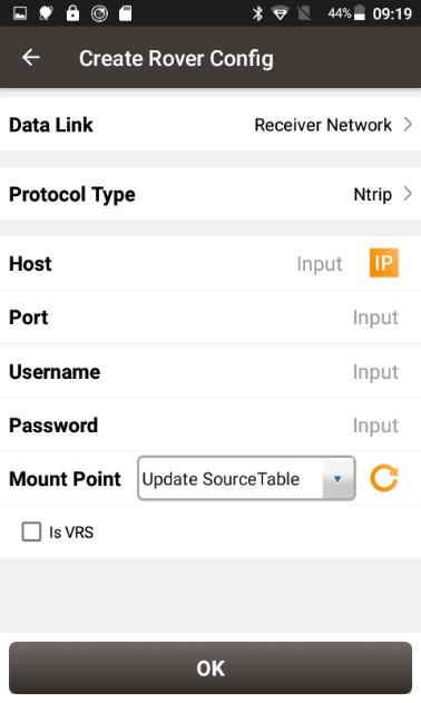
Figure 4.15[]{#_Toc6190 .anchor} Rover configuration - Receiver Network (Ntrip)
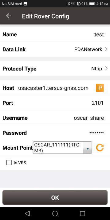
Figure 4.16[]{#_Toc13872 .anchor} Rover configuration - PDA Network (Ntrip)
Note: Select PDANetwork when using cellular or Wi-Fi network of a PDA such as TC50 Controller.
- After filling the information for the above configuration, click [OK]. Select this configuration in the work mode list and click [Start] to start data transmission for rover which is shown as below.

Figure 4.17[]{#_Toc13314 .anchor} Link status of Rover using internal radio
4.3 Static survey
Before performing static survey, ensure the battery has sufficient power and insert one SIM card when 4G/3G/2G network is required for operation.
Detailed steps of software operation:
-
Long press the power button to power on LUKA;
-
Use NFC function to launch Nuwa app. While the screen of TC50 Controller is unlocked, put TC50 Controller close to the LUKA NFC logo. The Bluetooth pairs automatically after a beep and Nuwa is launched requesting to open the latest project. Click [OK] and start configuring LUKA from step 6. Also you can click [Cancel] to create a new project or open an existing project, and then start configuring LUKA from step 6.
-
If using an android device without NFC function, ensure LUKA is powered on, and launch Nuwa application on the android device. Click [Project] in the main interface to create a new project or open an existing project and connect LUKA manually.
-
Back to the main interface of Nuwa app, click [Device] -> [Connect] under an opened project;
-
Select [LUKA] for the Device Type, select [Bluetooth] for the Connect Type, click [Connect Config] to search and pair the Bluetooth address of LUKA, select [LUKA] for the Antenna and click [Connect] to enable communication between the android controller and LUKA.
-
Click [Survey] -> [Static Survey], fill in the parameters of interval, cutoff angle, and etc. Then click [Start] to start static survey.
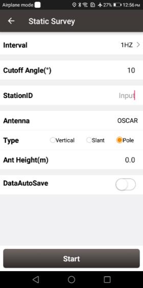 Figure 4.18[]{#_Toc13439 .anchor} Static Survey configuration
- If the DataAutoSave function is turned on, the static data is recorded automatically in the internal storage when power up LUKA next time. You can download data file refer to section 2.3.
4.4 Tilt survey and stakeout
Tilt function is only applicable for LUKA GNSS receiver Ultimate version under rover mode.
Tilt initialization
The tilt compensation of LUKA GNSS receiver Ultimate version is free of complex calibration. The tilt compensation will be initialized when the surveyor walks forward naturally for several meters after turning on the tilt compensation function. You can start tilt survey right after you walk to the survey point.
After the LUKA GNSS receiver Ultimate version is connect in Nuwa app, and we configure it working as a Rover. Click the device icon ![]() on the top or click [Device] under the device functional group to enter the device information interface. Turn on the [Tilt Enable] on the device interface.
on the top or click [Device] under the device functional group to enter the device information interface. Turn on the [Tilt Enable] on the device interface.
When tilt function is turned on, the tilt icon on the survey interface of NUWA app starts flashing red. At this time, walk a few steps ahead, tilt the pole at any direction, then the tilt icon turns [ON] which indicates tilt compensation is valid. Now you can start tilt survey.
When the tilt compensation is valid, click the Satellite info icon to view the detailed information of tilt compensation including tilt status, tilt direction, tilt angle, heading and their quality index. Among them, the tilt direct indicates which direction is tilted, that is, the angle between the projection of the ranging pole on the ground and the north direction after tilting; the tilt angle indicates the degree of tilt, that is, the angle between the tilted pole and the vertical direction; Heading indicates the surveyor's orientation (the facing of LUKA's back, we consider LUKA's panel is always facing the surveyor).
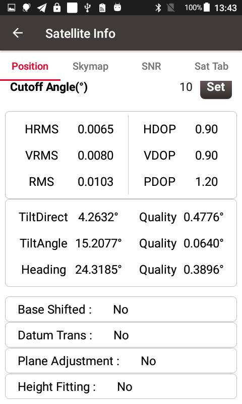
Figure 4.19[]{#_Toc18536 .anchor} Detailed information of tilt compensation
Tilt survey
After turning on [Tilt Enable] and tilt initialization is finished, enter Survey interface and start tilt survey.
The tilt status is displayed at the top of the survey interface. When the tilt status is ON, it is considered that the tilt compensation accuracy is high and it is in a usable state. You can start survey using the tilted ranging pole. Please ensure that the antenna height setting is correct which will affect the tilt measurement results.
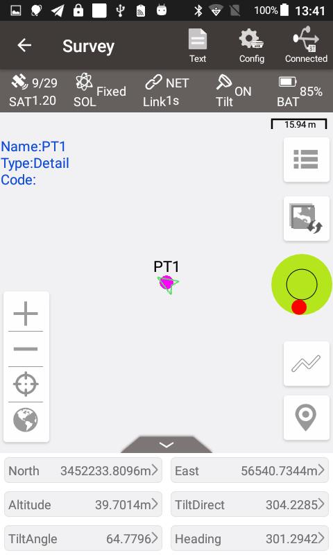
Figure 4.20[]{#_Toc13729 .anchor} Tilt status is ON
When the status is displayed as N/A and blinking, it is considered that the accuracy of tilt compensation is reduced and it is in a state that is not recommended. This may be caused by the surveyor standing for too long, rotating the ranging pole, or hitting the ranging pole to the ground. When the status is N/A, you need to redo the initialization. Generally, you do not need to stand still, just hold the ranging pole and walk forward to the next point, the initialization is complete automatically.
Note: during the tilt survey, please keep the LUKA OLED display facing the surveyor as much as possible. Please do not rotate the pole or hit the pole to the ground, which will invalidate the initialization or affect the accuracy of the tilt compensation. In addition, during the tilt point survey, if it does not continue at the third epoch reached when it is set smoothing 5 epochs for surveying points, please check whether the tilt compensation is invalid. It is not allowed to continue to complete the survey in the case where the tilt initialization accuracy is low.
Tilt stakeout
After turning on [Tilt Enable] and tilt initialization is finished, enter the Point Stakeout or Line Stakeout interface and start tilt stakeout. The tilt state is also added at the top of the stakeout interface to indicate the current tilt available state.
During the tilt stakeout process, if you enter the threshold range of the stakeout setting, the software will display a virtual tilt ranging pole along with the beep sounds. It is drawn according to the tilt direction angle. When the pole is tilted in a certain direction among east, west, south and north, the virtual tilt ranging pole on the interface will also tilt in a certain direction.
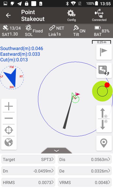
Figure 4.21[]{#_Toc14714 .anchor} Point stakeout when tilt compensation is on
4.5 Issues and solutions
This section lists possible issues and effective solutions to solve them. Please read this section before contacting Tersus technical support.
- LUKA GNSS receiver cannot receive satellite signals.
Solution:
(1) Change the survey environment, and restart LUKA in an open space.
1. The internal UHF radio does not transmit data.
Solution:
(1) Check whether the receiver is searching satellites normally;
(2) Check whether the radio antenna is installed properly;
(3) Check whether the radio module's protocol and channel are configured correctly and consistent with the configuration of rover's radio.
1. CORS network is not able to be logged in.
Solution:
Check whether the 4G SIM card is properly installed, and whether it can be used normally.
- The communication between Nuwa and LUKA fails.
Solution:
(1) Check whether the LUKA is powered on;
(2) Re-search and pair the Bluetooth;
(3) Upgrade Nuwa to the latest version.
1. There is no correction data for rover when using Ntrip work mode.
Solutions:
(1) Check whether the IP address, port, user name, password is correct;
(2) Check network. Try to use PDA/controller network to compare. Make sure there is no issue on the contact between the SIM card slot and the SIM card.
(3) Obtain the SourceTable to check the receiver network module, ensure there is no issue on CORS service.
(4) Try to log in with the same configuration and get a compared result if there is an extra receiver.
(5) If still cannot log in, consult your CORS service provider.
1. How to export static observation data from LUKA?
Solutions:
(1) Connect LUKA receiver with a computer through a Type-C to USB cable.
(2) The computer detects the LUKA receiver as an external disk.
(3) Open the Record folder, find the trs file and rinex file in its storage according to recording date.
(4) Copy the static observation data and paste them to the designated folder in your computer.
1. How to calibrate the E-Bubble of LUKA receiver?
Solutions:
(1) Firstly, install LUKA receiver on the tribrach of a tripod. Adjust the tribrach to enable the bubble to the center.
(2) Next step, select <Adjust> in the Nuwa under Device Info -> E-Bubble to complete the calibration.
1. How to apply Geoid model file correctly?
Solutions:
(1) Prepare the Geoid file at first and placed in the path of Internal storage\TersusSurvey\Geoid.
(2) Next step, launch Nuwa and go to select Project - Current Project and edit Coordinate System. Find the Height Fitting-Adjust Method and select Geoid.
(3) Last, select the file under Geoid List and apply it.
1. How to configure LUKA serial port output NMEA log?
Solutions:
(1) Nuwa can configure to output NMEA by the NMEA option. It can be specified the Baud Rate, the kind of sentence.
1. A base receiver is working well, the rover receiver cannot get correction data, how to fix this?
Solutions:
(1) Check whether the radio antenna connects well with receiver. Carefully check whether the interface is tightened.
(2) Check whether the air baud rate, Protocol, Bandwidth, Frequency match right with that of the base receiver.
(3) Switchover the radio frequency to avoid the possible interference from nearby devices.
1. The LUKA rover works at a short distance (not normal distance) at the radio mode?
Solutions:
(1) Check whether the rover connects a radio antenna.
(2) Adjust the radio of base at the high power gear.
(3) Check the environment if there exists radio interference along the propagation line.