2. General Operations
This chapter includes setting up, configuration and other related operations.
Setting up LUKA
2.1.1 Insert the SIM card
When 4G/3G/2G network is chosen for survey operation, you need to insert a nano SIM card into LUKA GNSS receiver. Insert the nano SIM card with the contacts facing outside which is shown as below.
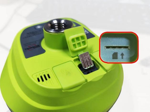
Figure 2.1[]{#_Toc13280 .anchor} Insert the SIM card
To eject the nano SIM card, slightly push it in to trigger the spring-loaded release mechanism.
Note: The SIM card is provided by your cellular network service provider.
2.1.2 Fix LUKA on a tripod or ranging pole
LUKA GNSS receiver has a standard 5/8'' x 11 UNC-2B connector and it can be fixed on a tripod or a ranging pole to be a base or rover according to customer requirement.
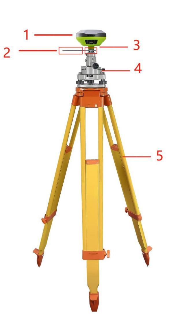
Figure 2.2[]{#_Toc1549 .anchor} LUKA as a base without radio antenna
Table 2.1[]{#_Toc17728 .anchor} Devices to set LUKA as a base without radio antenna
Device Name Quantity Items in the figure
LUKA GNSS receiver 1 1, details refer to section 1.3.1
Height measure accessory 1 2, details refer to section 1.3.6
GNSS antenna connector 1 3, details refer to section 1.3.6
Tribrach 1 4
Tripod 1 5
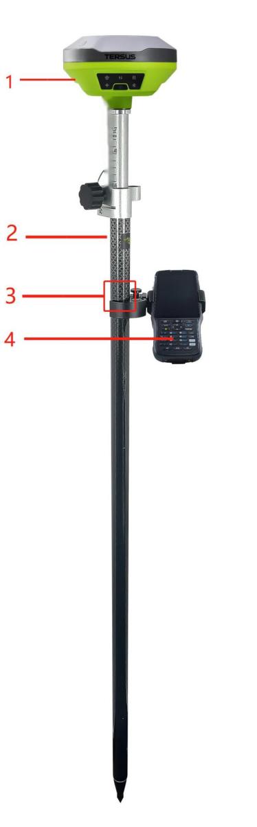
Figure 2.3[]{#_Toc7548 .anchor} LUKA as a rover without radio antenna
Table 2.2[]{#_Toc12256 .anchor} Devices to set LUKA as a rover without radio antenna
Device Name Quantity Items in the figure
LUKA GNSS receiver 1 1, details refer to section 1.3.1
Ranging pole 1 2, details refer to section 1.3.6
Bracket for TC50 1 3, details refer to section 1.3.6
TC50 Controller 1 4, details refer to section 1.3.4
2.2 LUKA configuration
You can configure LUKA GNSS receiver via button, TC50 controller or other android devices.
2.2.1 Configure via button
The detailed definition and configuration of button on LUKA GNSS receiver refers to section 1.3.1.
2.2.2 Configure via TC50 controller
The detailed introduction of TC50 controller refers to section 1.3.4 and technical specification refers section 3.2. Here in this section describes how to configure LUKA via Nuwa app which is installed in TC50 controller.
2.2.2.1 Connect LUKA in Nuwa
The general operations of Nuwa app refer to User Manual for Nuwa App which can be downloaded on Tersus official website.
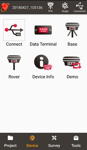
Figure 2.4[]{#_Toc25472 .anchor} Device functional group
When LUKA GNSS receiver is powered on, to connect LUKA, put TC50 controller near the NFC logo on LUKA, the TC50 controller pair Bluetooth with LUKA automatically; or click [Device] -> [Connect] under an opened project, and select [LUKA] for the Device Type which is shown as below.
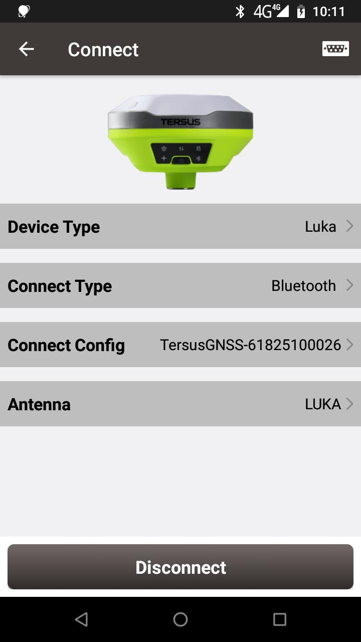
Figure 2.5[]{#_Toc2584 .anchor} Connect LUKA via Bluetooth
Select [Bluetooth] for the Connect Type. Click [Connect Config] to search and pair the Bluetooth address of LUKA. The antenna is selected as [LUKA] by default. Then click [Connect] to enable the communication between TC50 controller and LUKA.
2.2.2.2 Electronic Bubble (eBubble)
Make the body of LUKA stand on a leveled Tribrach before eBubble calibration. Click the device information icon ![]() on the top tool bar of Nuwa, the LUKA info is shown as below.
on the top tool bar of Nuwa, the LUKA info is shown as below.
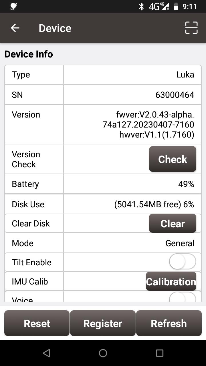
Figure 2.6[]{#_Toc25064 .anchor} Device info of LUKA
Click ![]() on the right of electronic bubble to adjust bubble. On the screenshot below, the eBubble is not in the black circle and its color is red for warning purpose.
on the right of electronic bubble to adjust bubble. On the screenshot below, the eBubble is not in the black circle and its color is red for warning purpose.
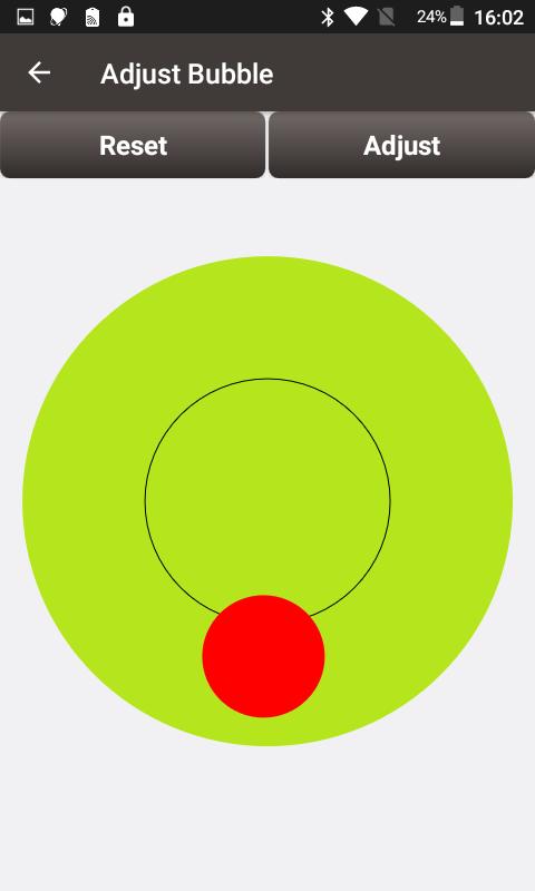
Figure 2.7[]{#_Toc25871 .anchor} eBubble before adjusting
Click ![]() on the right, the eBubble is calibrated to the center inside the black circle and the bubble color turns blue.
on the right, the eBubble is calibrated to the center inside the black circle and the bubble color turns blue.
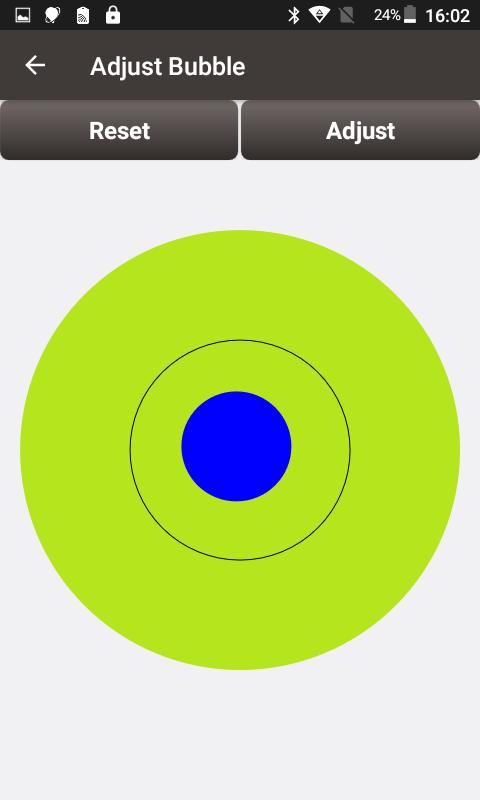
Figure 2.8[]{#_Toc17821 .anchor} eBubble after adjusting
2.2.2.3 Registration
When the registration is not effective, follow below steps to complete the registration by using QR code.
Click the scan button at the top right of the device information interface and directly scan the QR code provided by Tersus to complete the registration.
2.2.2.4 Configure base or rover
To configure LUKA as a base or rover, back to Device interface which is shown in Figure 2.4 Device functional group, click [Base] or [Rover], then create a work mode of detailed configurations for base or rover which are shown as below.
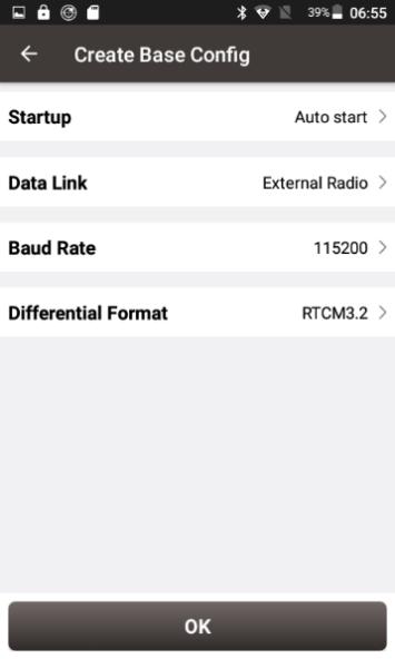
Figure 2.9[]{#_Toc1199 .anchor} Base configuration
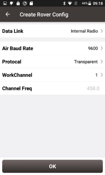
Figure 2.10[]{#_Toc32639 .anchor} Rover configuration
Fill in the detailed information of base configuration or rover configuration, then click [OK] and back to the work mode list, select this configuration to start data transmission for base or rover which are shown as below.
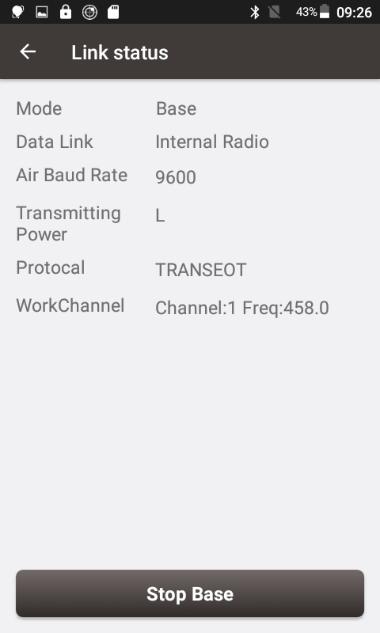
Figure 2.11[]{#_Toc2541 .anchor} Link status of Base
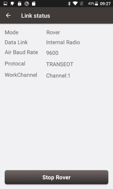
Figure 2.12[]{#_Toc10821 .anchor} Link status of Rover
2.3 Data download
2.3.1 Connection
LUKA can be used as an USB storage device when connecting with a computer. Before connecting LUKA to a computer, ensure LUKA is powered on. Use the Type-C to USB cable in the package to connect LUKA to the USB port of a computer which is shown as below.
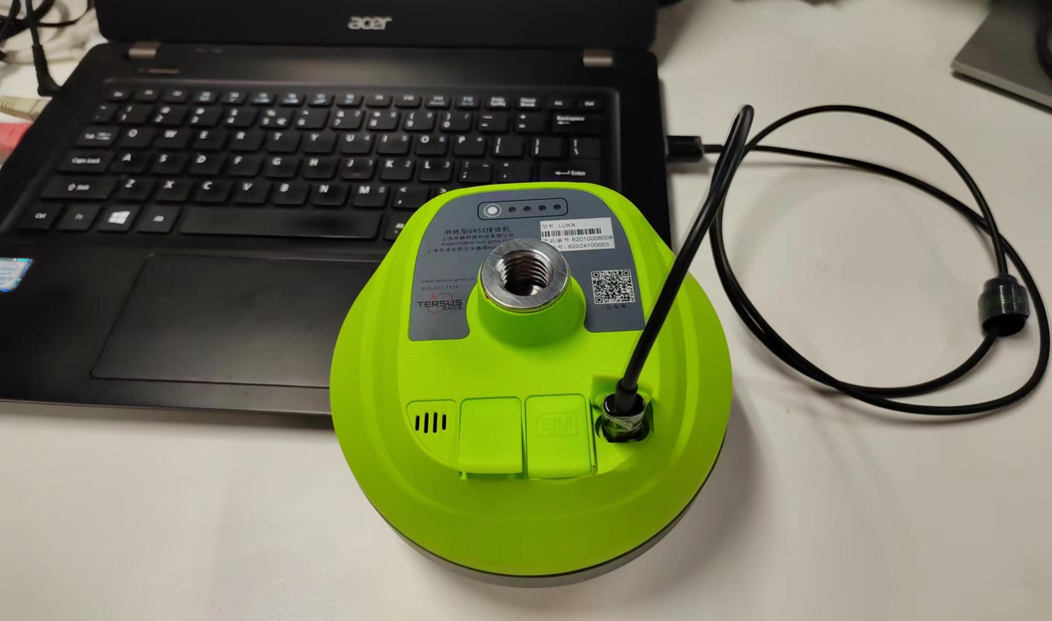
Laptop
Figure 2.13[]{#_Toc26710 .anchor} Connect LUKA to a computer
After completing the connection, a USB device is listed in the file browser of the computer. Find the data file needed to download, copy and paste it to a designated folder in your computer.
2.3.2 Download static data
If you want to download the recorded static data for post processing, find record folder shown as below, and then copy the specific file you need to your computer.
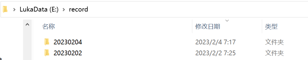
Figure 2.14[]{#_Toc29202 .anchor} Static record folder
Each folder named after the date contains rinex format and tersus binary data, which can be downloaded and processed as you need.
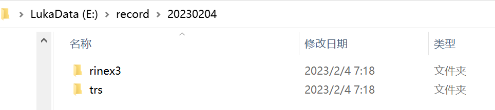
Figure 2.15[]{#_Toc10825 .anchor} Static data for one day
2.3.3 Download debug data
When you don't turn on the debug mode, find debug\LOG folder and you can see rtkmain.log file which includes all the operation information of the receiver.
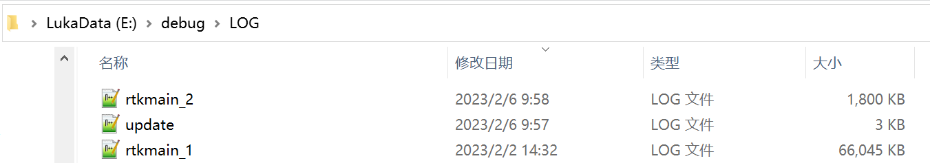
Figure 2.16[]{#_Toc6729 .anchor} rtkmain.log file location
To turn on the debug mode, you can click [Device] -> [Device Debug] -> [Set] in Nuwa app. The debug information includes GNSS, tilt, internal radio and NTRIP information. Select the debug info you want to record and turn on the debug mode. After you select some debug info to turn on and confirm, LUKA will record them when you are doing survey work.
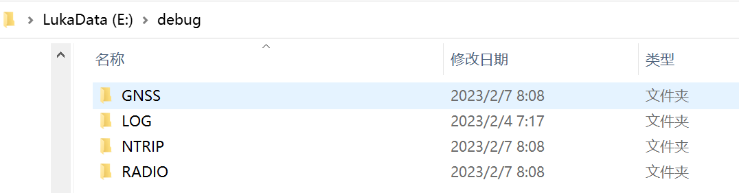
Figure 2.17[]{#_Toc17764 .anchor} Debug info folders
Send these debug info to Tersus technical support team to help solve the problems you encountered.
2.4 Firmware upgrade
View LUKA firmware version. When LUKA GNSS receiver is powered on, to connect LUKA, put controller near the NFC logo on LUKA, the controller pair Bluetooth with LUKA automatically; or click [Device] -> [Connect] under an opened project, and select [LUKA] for the Device Type, select [Bluetooth] for the Connect Type. Click [Connect Config] to search and pair the Bluetooth address of LUKA. The antenna is selected as [LUKA] by default. Then click [Connect] to enable the communication between controller and LUKA.
Figure 2.18[]{#_Toc5539 .anchor} Connect to LUKA via Bluetooth
Click the device information icon ![]() on the top tool bar of Nuwa, the LUKA info is shown as below. You can view LUKA firmware version.
on the top tool bar of Nuwa, the LUKA info is shown as below. You can view LUKA firmware version.
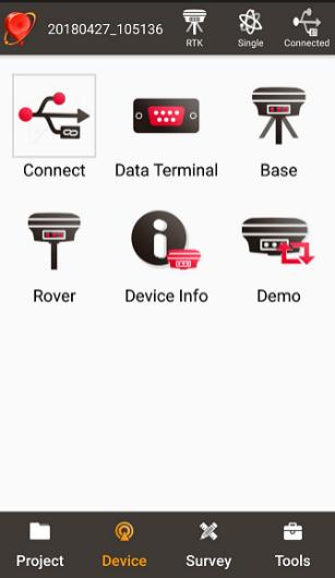
Figure 2.19[]{#_Toc4924 .anchor} View LUKA firmware version
The detailed steps are as follows.
-
Download the latest firmware file from Tersus website [https://www.tersus-gnss.com/software/LUKA-gnss-receiver.]
Please be noted that the downloaded file is a .zip file, unzip this file to find the firmware file of .BIN format.
-
Prepare a Type-C to USB cable, when LUKA is turned on, connect the Type-C port of LUKA to the computer with a Type-C to USB cable.
Figure 2.20[]{#_Toc25727 .anchor} connect the computer and LUKA
- The computer interface will automatically pop up two removable disks. As shown in the figure below.

Figure 2.21 Two Removable Disks
-
Choose the LUKAUpdate removable disk and put the firmware file in the .BIN format on this removable disk. As shown in the figure below.

Figure 2.22 The FW is placed in the LUKAUpdate removable disk
-
Unplug the Type-C to USB cable, press and hold the power button for 3 seconds to shut down LUKA .
6) Make sure that LUKA is turned off, then press and hold the power button for 2 seconds to turn on LUKA.
When the six indicators on the LED panel are all on, the boot is successful, release the power button. LUKA enters the upgrade mode when the six indicators on the LED panel are all on again, and waits for the upgrade to complete.
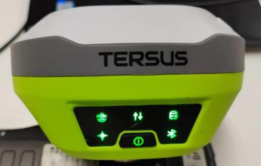
Figure 2.23 Upgrading
After the firmware upgrade is completed, the power LED light is on and the satellite light flashes. At this time, you can check the LUKA firmware version. If it is consistent with the latest firmware version in the removable disk, the firmware upgrade is successful.
Note: Please make sure the battery has enough power for the firmware upgrade. The GNSS board inside LUKA will upgrade when the firmware is upgrading, any forced power failure will cause the system crash.
2.5 Web UI
LUKA GNSS receiver supports being a Wi-Fi hot spot and connect with a computer or a smart terminal within five meters. You can read coordinate information, configure the receiver and upgrade the firmware through the web UI (user interface) on the browser of the computer or the smart terminal.
Follow below steps to enter the web user interface on a computer with Windows 10 operating system.
a. Upgrade the receiver to the latest firmware, and then open Wi-Fi .
Switch to [Device] -- [WIFI Setting] -- [Set] -- [Mode Config], select [AP] -- [confirm] via NUWA, as shown below.
Note: the version of NUWA app must be upgraded to V2.3.3 or above.
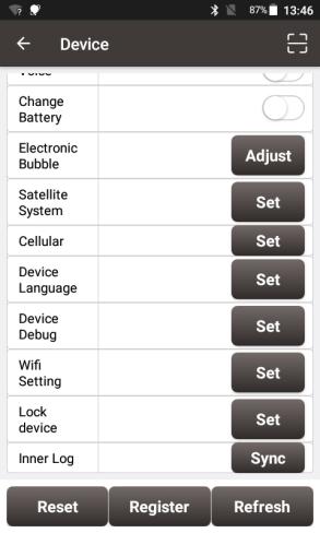

Figure 2.24 WiFi interface
b. Click the Internet connection icon on the lower right corner of the desktop. Turn on Wi-Fi connection and search the SSID of LUKA GNSS receiver which is composed of TersusGNSS and an eight digit number such as below. Click [Connect] to complete the Wi-Fi connection.
 Figure 2.25 Make Wi-Fi connection
c. Open a web browser and type 192.168.2.1 in the address bar. Type "admin" for the username and password, then click [Sign in] to enter the web UI.
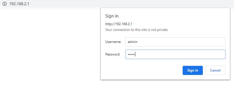 Figure 2.26 Sign in the web UI
d. When you entered the web UI of LUKA GNSS receiver, you can see eight tabs on the left and make corresponding operations such as view positioning info, view satellites info, make device settings, make connectivity settings, and upgrade firmware. [Receiver Status] - [Position] - view position information.
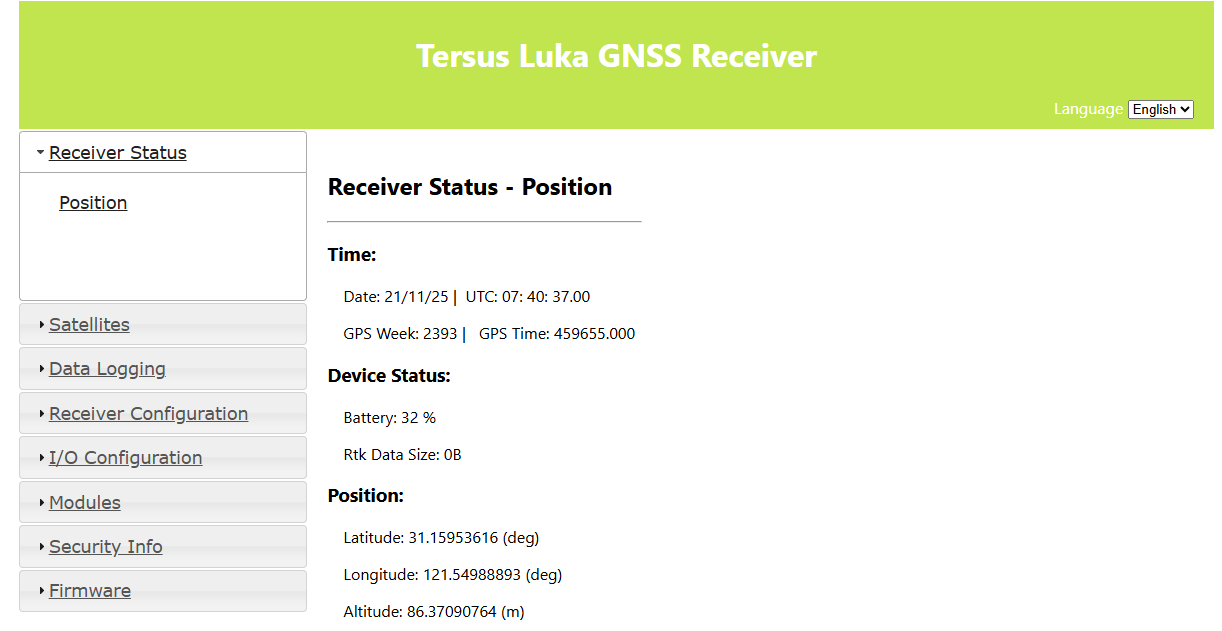
Figure 2.27 Main interface of LUKA's web UI
e. configure the working mode and related parameters of LUKA in [Receiver Configuration].
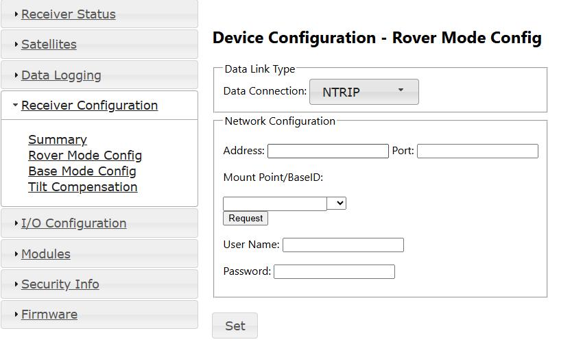
Figure 2.28 configure a working mode
To enable tilt compensation, turn on Tilt Mode in in [Tilt Compensation] settings. Make sure the pole height is configured correctly.
If the tilt correction on GGA is also enabled, the GGA messages will no longer record the coordinates of the phase center of the antenna in the tilted state, but the coordinates of the virtual phase center, which is the ground point coordinates plus the antenna height, assuming that the pole is vertical.
f. configure NMEA data output in [I/O Configuration] - [Port Configuration]
In NMEA out Settings, the configuration of the NMEA messages output frequency will take effect for both serial output and Bluetooth output.
In Localized Coordinates Configuration, select your local coordinate system, and the localized coordinates will be output in NMEA PJK messages.
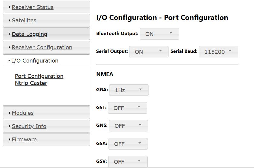
Figure 2.29 configure NMEA data output
g. configure connectivity.
[Modules] - [Cellular Network] - enter APN Name - set.
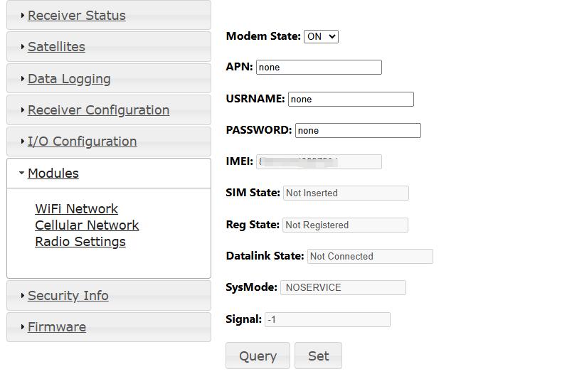
Figure 2.30 configure connectivity
h. upgrade device firmware version via web page
\[Firmware\] - \[Firmware Info\] - \[Firmware Upgrade\] - click to select the file - click \[upgrade\].
you can use this function to upgrade after the next official version is released.
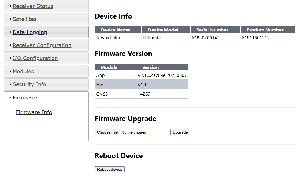
Figure 2.31 upgrade the firmware
i. manage user logins through web pages.
[Security Info] - [Account Info] - [Add User] - [Add User Dialog] - input Login Name&Alias Name&Password.
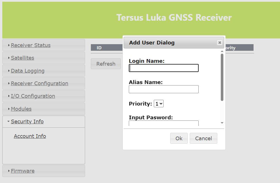
Figure 2.32 add user login
2.6 Operations of TC50 controller
2.6.1 Insert SIM card and SD card
Please note the direction of the card notch when inserting the card, inserting a non-standard card may cause damage to the SIM card slot of the controller.
The controller cannot support two CDMA cards at the same time, when two CDMA cards are installed at the same time, only one card can use the 4G network, the other card will not be able to register the network.
To install the SIM card you need to open the battery cover, remove the battery and open the SIM card cover.
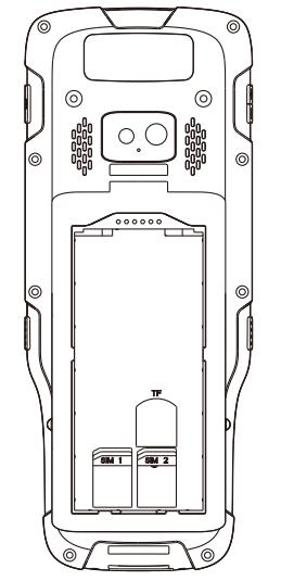
Figure 2.33 Install the SIM card
Note: Please power off the controller before plug in or pull out the SIM card.
2.6.2 Using of touch screen
-
Single Click: To select an icon. For example, click dial to open the keypad which will be displayed on the screen.
-
Double Click: To zoom-in or zoom-out. For example, to zoom-in or out of a photo, click twice when viewing a photo or browsing on the internet.
-
Hold: press and hold the screen, icon or input box to get more operation options.
a) Long-Time Click a picture in the gallery list interface, the status bar prompts to select a picture, you select to share or delete it.
b) Long-Time Click the blanks of home screen to add home screen widgets.
c\) Long-Time Click the blanks of home screen wallpaper sources can be selected.

d\) Long-Time Click the blanks of home screen to home settings.

-   **Slide Upward:** Slide up on the main screen ( or click the upward arrow icon) to view more applications.

-   **Slide Downward:** Slide down on any interface to open the status bar and message board.

-   **Slide Left and Right:** Slide left and right on the main screen to switch the desktop interface.