Functions
This chapter describes the detailed operations of Tersus GNSS Center
Before using Tersus GNSS Center software, ensure one BX board or one receiver of David series GNSS Receiver is powered up and connected to the computer via serial port. The physical connection refers to corresponding user manual which can be downloaded from Tersus website
https://tersus-gnss.com/document.
2.1 Config window
When launching Tersus GNSS Center, the config window pops up automatically. This window can also be found in the menu bar Tools -> Config.
2.1.1 Connection
Under the connection tab, there are two options:
- Serial
If choosing Serial as connection type, choose the right port when a Tersus GNSS board or receiver is connected to computer via serial port. The serial port can be found in the windows device manager and obtained by clicking
and then selected in the drop-down list.
The baud rate is 115200 bps by default. It is not recommended to change baud rate. The 'Save Received Data' function is turned on by default. It can be turned off manually.
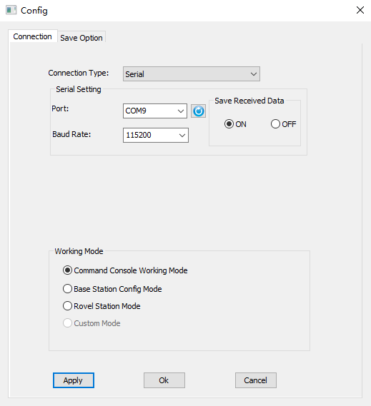
Figure 2.1[]{#_Toc22788 .anchor} Connection config -- serial connection
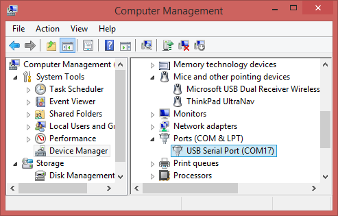 Figure 2.2[]{#_Toc12984 .anchor} Device manager
- Demo file
If choosing demo file as connection type, click the file path and choose the demo file, selecting loop can play the demo repeatedly, then click [OK] to start playing demo file. The demo file can be .trs, .nmea, .dat format files.
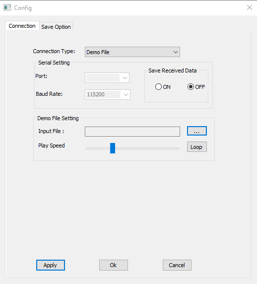
Figure 2.3[]{#_Toc15451 .anchor} Connection config -- demo file
2.1.2 Working mode
There are three working mode to choose: command console working mode, base station config mode, and rover station mode.
- Command console working mode
This mode is the major mode that is introduced in this user manual.
- Base station config mode
If choosing base station config mode, it pops out below config window. Configuring parameters for base station by selecting in drop-down options is another method which is different from command configuration.
You can fill in the coordinates of the base station or tick Posave on to enable auto base station.
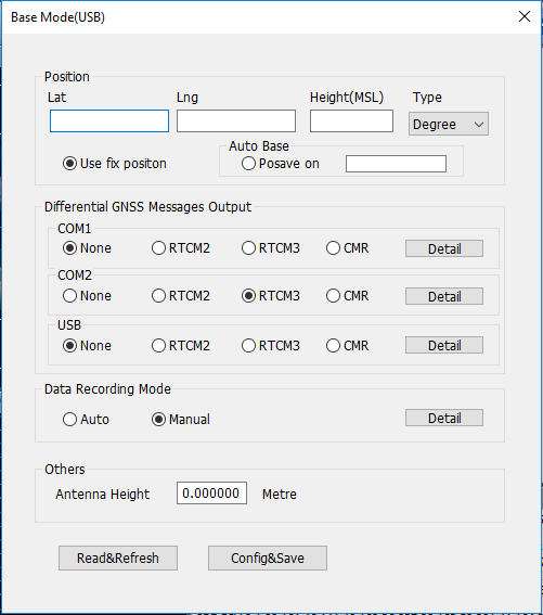 Figure 2.4[]{#_Toc622 .anchor} Base mode configuration
For differential GNSS message output, you can configure RTCM2, RTCM3 or CMR message for the current communication port. Click [Detail] to configure corresponding message types.
 Figure 2.5[]{#_Toc12694 .anchor} Options for RTCM2
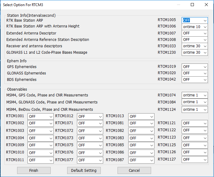
Figure 2.6[]{#_Toc6382 .anchor} Options for RTCM3
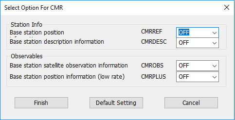
Figure 2.7[]{#_Toc18363 .anchor} Options for CMR
For data recording mode, you can choose auto or manual, click [Detail] to configure corresponding output options.
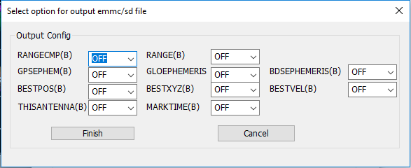 Figure 2.8[]{#_Toc27140 .anchor} Output options
You can also set antenna height under Others. Click [Config&Save] to finish the base mode configuration.
- Rover station mode
If choosing rover station config mode, it pops out below config window. In the rover mode configuration interface, you can configure rover's output from COM1/COM2/USB/File.
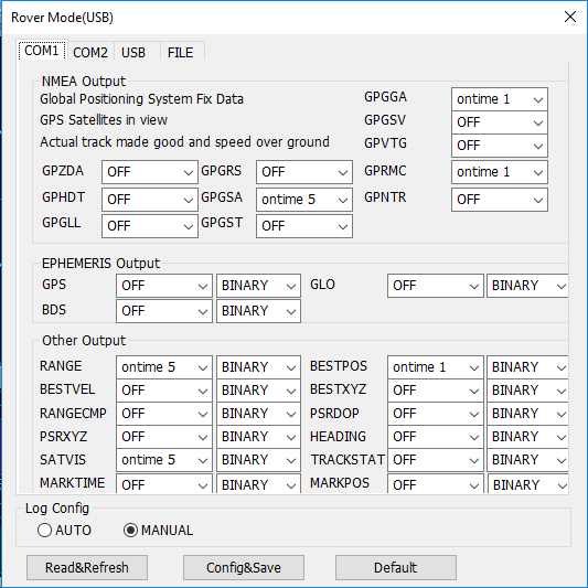 Figure 2.9[]{#_Toc25238 .anchor} Configure COM1 for rover mode
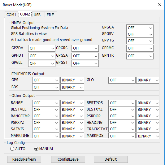 Figure 2.10[]{#_Toc22140 .anchor} Configure COM2 for rover mode
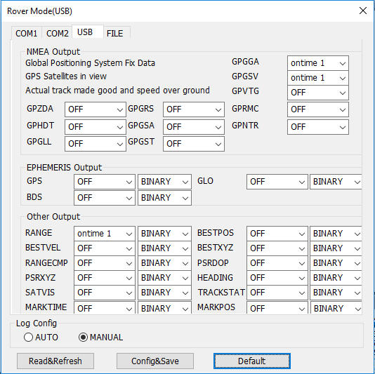 Figure 2.11[]{#_Toc15613 .anchor} Configure USB for rover mode
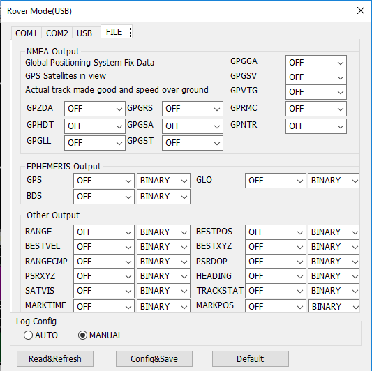 Figure 2.12[]{#_Toc24715 .anchor} Configure FILE for rover mode
After setting all required parameters, click [Config&Save] to finish the rover mode configuration.
2.1.3 Save option
Under the save option tab, the output directory can be set, the data format options can be checked according to different requirement. The log option is .log by default.
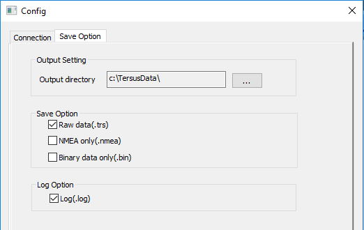
Figure 2.13[]{#_Toc24664 .anchor} Save option config
2.2 Interface and functions
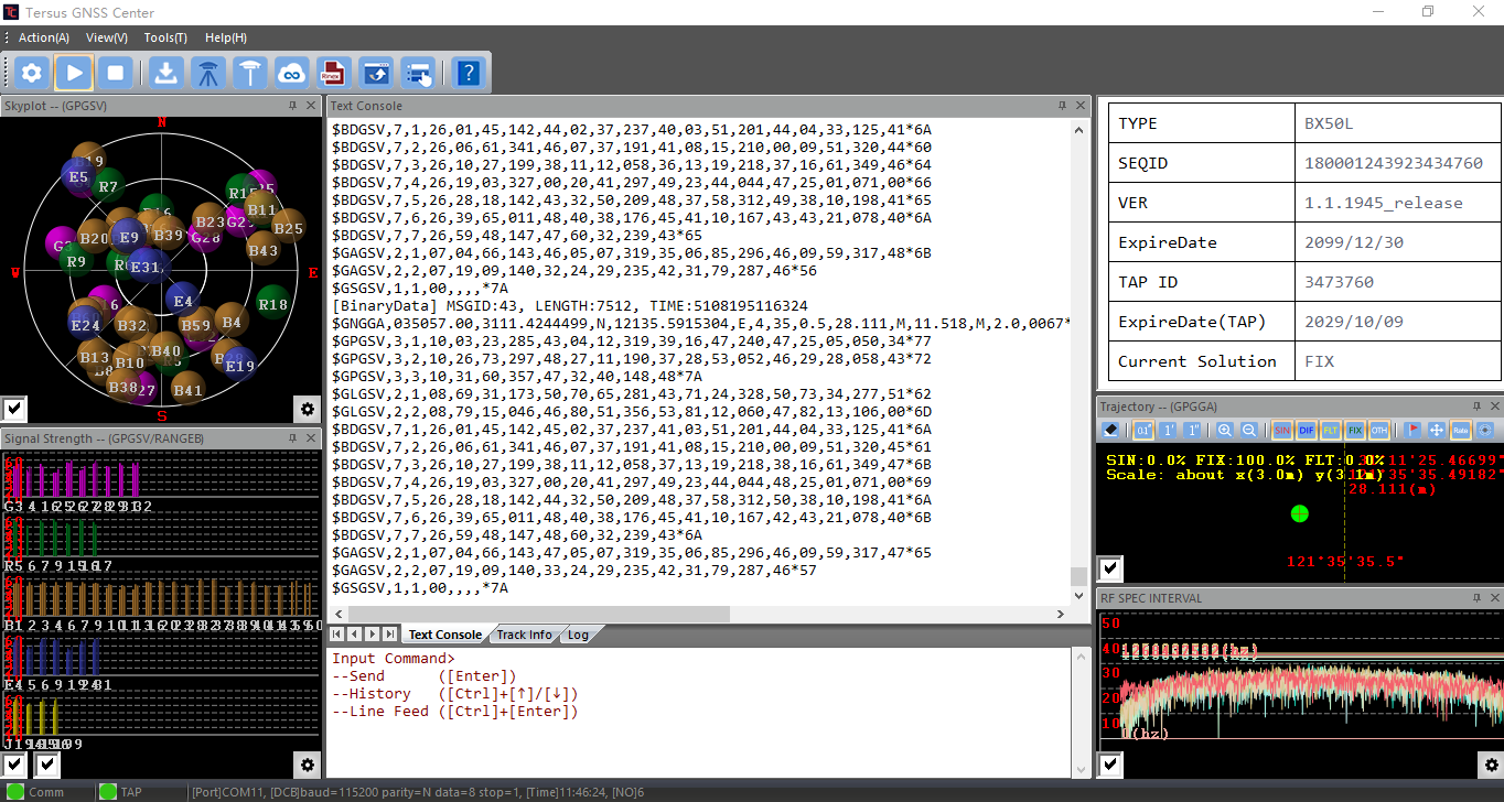
The main interface of Tersus GNSS Center is shown as below.
2. Tool bar
1. Menu bar
6. Command window
10. Status bar
5. Console window
- RF SPEC
8. Trajectory
7. Board Info
4. Signal strength
3. Skyplot
Figure 2.14[]{#_Toc32618 .anchor} Tersus GNSS Center main interface
2.2.1 Menu bar
The menu bar includes below options:
- Action
Under the action tab, it has three options: Play, Stop and Quit.
- View
Under the view tab, it has five options: Restore Layout, Windows, Status Bar, Skin and Map.
Restore Layout restore layout of interface after the software restart
Windows check which window to display
Status Bar check to display or not display status bar at the bottom
Skin choose from seven skin types for this software
Map display Google map in the board information window
- Tools
Under the tools tab, it has three categories:
a. Config, Peferences, Base Station Config, Rover Station Config, Ntrip Config and Output Config;
b. Show position summary, Pin output, and Erase Trajectory;
c. RINEX Converter and Update Firmware.
<!-- -->
- Help
Under the help tab, it shows the Tersus GNSS Center version.
2.2.2 Tool bar
The tool bar shows different tools in icons.
+-----------------------------------------------------------------------------------------------------------------------------------------------------+----------------------------------------------------------------------------------------------------------------------------------------------------------------------------------------------------------------------------------------------------------+
| ![]() | configure connection and save option, details refer to section 2.1. |
+-----------------------------------------------------------------------------------------------------------------------------------------------------+----------------------------------------------------------------------------------------------------------------------------------------------------------------------------------------------------------------------------------------------------------+
|
| configure connection and save option, details refer to section 2.1. |
+-----------------------------------------------------------------------------------------------------------------------------------------------------+----------------------------------------------------------------------------------------------------------------------------------------------------------------------------------------------------------------------------------------------------------+
| ![]() | enable the serial port connection, or play the demo file. |
+-----------------------------------------------------------------------------------------------------------------------------------------------------+----------------------------------------------------------------------------------------------------------------------------------------------------------------------------------------------------------------------------------------------------------+
|
| enable the serial port connection, or play the demo file. |
+-----------------------------------------------------------------------------------------------------------------------------------------------------+----------------------------------------------------------------------------------------------------------------------------------------------------------------------------------------------------------------------------------------------------------+
| ![]() | disable the serial port connection, or stop playing the demo file. |
+-----------------------------------------------------------------------------------------------------------------------------------------------------+----------------------------------------------------------------------------------------------------------------------------------------------------------------------------------------------------------------------------------------------------------+
|
| disable the serial port connection, or stop playing the demo file. |
+-----------------------------------------------------------------------------------------------------------------------------------------------------+----------------------------------------------------------------------------------------------------------------------------------------------------------------------------------------------------------------------------------------------------------+
| ![]() | set the data saving type and saving path, details refer to section 2.1.3. |
+-----------------------------------------------------------------------------------------------------------------------------------------------------+----------------------------------------------------------------------------------------------------------------------------------------------------------------------------------------------------------------------------------------------------------+
|
| set the data saving type and saving path, details refer to section 2.1.3. |
+-----------------------------------------------------------------------------------------------------------------------------------------------------+----------------------------------------------------------------------------------------------------------------------------------------------------------------------------------------------------------------------------------------------------------+
| ![]() | base mode config, details refer to section 2.1.2. |
+-----------------------------------------------------------------------------------------------------------------------------------------------------+----------------------------------------------------------------------------------------------------------------------------------------------------------------------------------------------------------------------------------------------------------+
|
| base mode config, details refer to section 2.1.2. |
+-----------------------------------------------------------------------------------------------------------------------------------------------------+----------------------------------------------------------------------------------------------------------------------------------------------------------------------------------------------------------------------------------------------------------+
| ![]() | rover mode config, details refer to section 2.1.2. |
+-----------------------------------------------------------------------------------------------------------------------------------------------------+----------------------------------------------------------------------------------------------------------------------------------------------------------------------------------------------------------------------------------------------------------+
|
| rover mode config, details refer to section 2.1.2. |
+-----------------------------------------------------------------------------------------------------------------------------------------------------+----------------------------------------------------------------------------------------------------------------------------------------------------------------------------------------------------------------------------------------------------------+
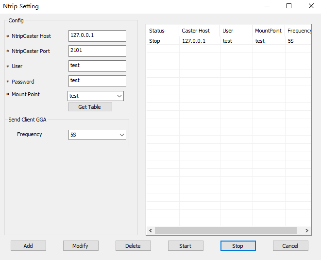
| ![]() | Ntrip settings, to receive correction data and forward the NTRIP correction data received to the board. Enter Ntrip parameters host, port, username, password and mount point, and add the configuration to the list on the right then start the stream. |
| | |
| |
| Ntrip settings, to receive correction data and forward the NTRIP correction data received to the board. Enter Ntrip parameters host, port, username, password and mount point, and add the configuration to the list on the right then start the stream. |
| | |
| |  |
| | |
| | Figure 2.15[]{#_Toc13664 .anchor} Ntrip Setting |
+-----------------------------------------------------------------------------------------------------------------------------------------------------+----------------------------------------------------------------------------------------------------------------------------------------------------------------------------------------------------------------------------------------------------------+
|
|
| | |
| | Figure 2.15[]{#_Toc13664 .anchor} Ntrip Setting |
+-----------------------------------------------------------------------------------------------------------------------------------------------------+----------------------------------------------------------------------------------------------------------------------------------------------------------------------------------------------------------------------------------------------------------+
| ![]() | open Tersus Rinex Converter, details refer to section 2.3.3. |
+-----------------------------------------------------------------------------------------------------------------------------------------------------+----------------------------------------------------------------------------------------------------------------------------------------------------------------------------------------------------------------------------------------------------------+
|
| open Tersus Rinex Converter, details refer to section 2.3.3. |
+-----------------------------------------------------------------------------------------------------------------------------------------------------+----------------------------------------------------------------------------------------------------------------------------------------------------------------------------------------------------------------------------------------------------------+
| ![]() | open Tersus Update for firmware upgrade, details refer to section 2.3.4. |
+-----------------------------------------------------------------------------------------------------------------------------------------------------+----------------------------------------------------------------------------------------------------------------------------------------------------------------------------------------------------------------------------------------------------------+
|
| open Tersus Update for firmware upgrade, details refer to section 2.3.4. |
+-----------------------------------------------------------------------------------------------------------------------------------------------------+----------------------------------------------------------------------------------------------------------------------------------------------------------------------------------------------------------------------------------------------------------+
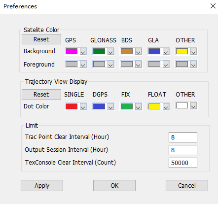
| ![]() | set environment preferences as shown below. Set satellite color, set trajectory view display colors, set limit for tracing point clear interval, set limit for output session interval, and set text console clear interval. |
| | |
| |
| set environment preferences as shown below. Set satellite color, set trajectory view display colors, set limit for tracing point clear interval, set limit for output session interval, and set text console clear interval. |
| | |
| |  |
| | |
| | Figure 2.16[]{#_Toc22084 .anchor} Set environment preferences |
+-----------------------------------------------------------------------------------------------------------------------------------------------------+----------------------------------------------------------------------------------------------------------------------------------------------------------------------------------------------------------------------------------------------------------+
|
|
| | |
| | Figure 2.16[]{#_Toc22084 .anchor} Set environment preferences |
+-----------------------------------------------------------------------------------------------------------------------------------------------------+----------------------------------------------------------------------------------------------------------------------------------------------------------------------------------------------------------------------------------------------------------+
| ![]() | view Tersus GNSS Center version, click Update Software to open Tersus website to check the new version of software. |
| | |
| |
| view Tersus GNSS Center version, click Update Software to open Tersus website to check the new version of software. |
| | |
| |  |
| | |
| | Figure 2.17[]{#_Toc4646 .anchor} Tersus Center Version |
+-----------------------------------------------------------------------------------------------------------------------------------------------------+----------------------------------------------------------------------------------------------------------------------------------------------------------------------------------------------------------------------------------------------------------+
|
| | |
| | Figure 2.17[]{#_Toc4646 .anchor} Tersus Center Version |
+-----------------------------------------------------------------------------------------------------------------------------------------------------+----------------------------------------------------------------------------------------------------------------------------------------------------------------------------------------------------------------------------------------------------------+
2.2.3 Skyplot view
The Skyplot view displays the number of GNSS systems (GPS / GLONASS / Beidou / Galileo / QZSS) and TAP satellites tracked by the board or receiver and their elevation / azimuth angle. The different GNSS constellations are distinguished with different colors, which can be configured in Tools -﹥Preference. The satellite PRN are marked in the figure with capitalized character 'G', 'R', 'B', 'E', 'J', 'T' referring GPS, GLONASS, Beidou, Galileo, QZSS and TAP satellites constellation respectively. The figure is expressed in polar coordinate system with its direction refers to the azimuth angle and radius refers to its zenith distance (90-elevation angle in degree). Please note the view works only when GPGSV message and TAP satellite message is logged.
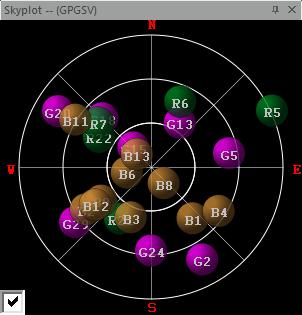
Figure 2.18[]{#_Toc21074 .anchor} Skyplot view
2.2.4 Signal strength view
The Signal strength view shows the signal noise ratio of different frequencies of corresponding GNSS systems (GPS/GLONASS/Beidou/Galileo/QZSS) and TAP satellites. The horizontal axes represent the number and the PRN. The vertical axes represent the carrier to noise ratio (C/N0) in dB/Hz. Note: the receiver is capable of tracking multiple frequency signals for some constellation, check the box at the bottom left corner to present the C/N0 of different frequency signals. Please note the view works only when GPGSV message and TAP satellite message is logged.

Figure 2.19[]{#_Toc26967 .anchor} Signal strength view
2.2.5 Console window
The console window has three tabs: Text Console, Track Info and Log.
- The Text console window provides a way for users to communicate directly with the board. Commands can be sent to the board using this window and all ASCII-format messages are displayed. When binary format data is received, the Text console window will show a summary of the binary data, including message type and data length. If the unrecognizable characters are received, they will be considered as error log and shown in Log view.
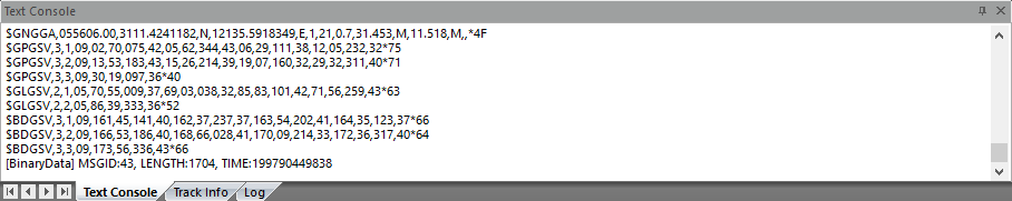
Figure 2.20[]{#_Toc29765 .anchor} Text console window
- The track info window provides the coordinates at a frequency of 1Hz.
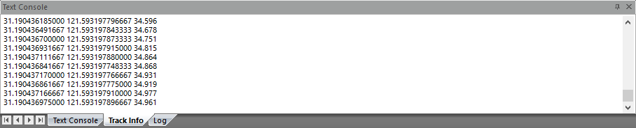
Figure 2.21[]{#_Toc32447 .anchor} Track info window
- The log window lists output messages of ASCII or abbreviated ASCII format.
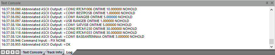
Figure 2.22[]{#_Toc18660 .anchor} Log window
2.2.6 Command window
The command window is to input/type commands. Press Enter to send the commands to the boards or receivers. Press Ctrl + Up/Down to get history commands. Press Ctrl + Enter to perform a line feed.

Figure 2.23[]{#_Toc17677 .anchor} Command window
2.2.7 Board Info
The type, serial number, firmware version, expire date, TAP ID, expire date of TAP service and current solution of the GNSS board connected will be displayed as shown below.
Figure 2.24[]{#_Toc21750 .anchor} Board Information
Click [View] - [Map] to display Google map as shown below, to show the current position on the map.
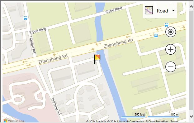
Figure 2.25[]{#_Toc18646 .anchor} Map View
2.2.8 Trajectory view
The Trajectory view provides real-time graphic plotting of the current horizontal position (longitude and latitude). Different solution status are presented in different colors, which are defined as:
-
SIN (Single point positioning solution)
-
DIF (DGPS solution)
-
FLT (RTK float solution)
-
FIX (RTK fixed solution)
-
OTH (others solution status , e.g. Dead Reckoning or invalid solution)
You can turn on certain type of solution status via tool bar or click the erase to clear the trajectory. Please note the view works only when GPGGA message is logged.
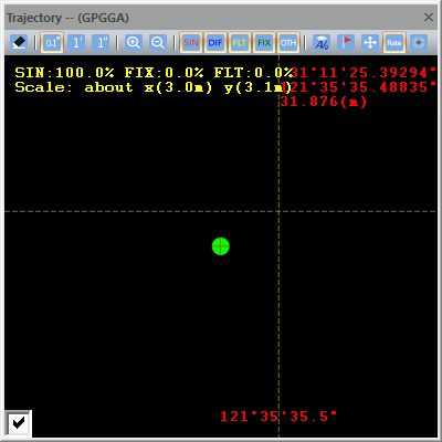
Figure 2.26[]{#_Toc30818 .anchor} Trajectory view
2.2.9 RF spectrum view
The RF SPEC INTERVAL view displays interference at different frequencies for different satellite systems. Clicking on the setting icon in the lower right corner to display interference on a certain frequency of a certain satellite system. When strong interference is present, the wave show anomalies and approaches or breaks the horizontal line. Please note the view works only when RFSPECTRUMCONTROL message is enabled.
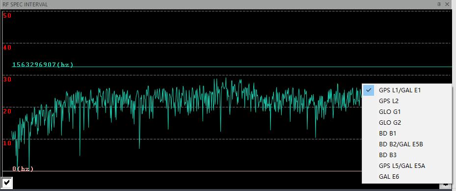
Figure 2.27[]{#_Toc19676 .anchor} RF spectrum view
2.2.10 Status bar
Tersus GNSS Center indicates the working status of the board or receiver with a group of indicators and connection status on the status bar at the bottom of the main interface.
![]()
Figure 2.28[]{#_Toc3221 .anchor} Indicators
Table 2[]{#_Toc31206 .anchor} Indicators description
Indicator Status Description
Comm Red Tersus GNSS Center is not connected to the board
Green Tersus GNSS Center is well connected to the board
TAP Red TAP is not supported
              Yellow         TAP is supported but expired

              Green          TAP is supported and available
![]()
Figure 2.29[]{#_Toc31631 .anchor} Connection status
2.2.11 Other views
Click [View] - [Windows] to display more views, including Altitude, Time (UTC), Velocity and Heading. Please notice that the unit of attitude is meter and that of velocity is km/h . The time system is UTC time and the time shows in the figure may be different from your local time. Please note these views work only when GPGGA, GPVTG and HEADINGA / HEADINGB message is logged.
+---------------------------------------------------------------------------------------------------------------------------------------------------+---------------------------------------------------------------------------------------------------------------------------------------------------+
|  |
|  |
| | |
| Figure 2.30[]{#_Toc16932 .anchor} Altitude info | Figure 2.31[]{#_Toc20948 .anchor} UTC time |
+---------------------------------------------------------------------------------------------------------------------------------------------------+---------------------------------------------------------------------------------------------------------------------------------------------------+
|
|
| | |
| Figure 2.30[]{#_Toc16932 .anchor} Altitude info | Figure 2.31[]{#_Toc20948 .anchor} UTC time |
+---------------------------------------------------------------------------------------------------------------------------------------------------+---------------------------------------------------------------------------------------------------------------------------------------------------+
|  |
|  |
| | |
| Figure 2.32[]{#_Toc434 .anchor} Velocity info | Figure 2.33[]{#_Toc9990 .anchor} Heading info |
+---------------------------------------------------------------------------------------------------------------------------------------------------+---------------------------------------------------------------------------------------------------------------------------------------------------+
|
| | |
| Figure 2.32[]{#_Toc434 .anchor} Velocity info | Figure 2.33[]{#_Toc9990 .anchor} Heading info |
+---------------------------------------------------------------------------------------------------------------------------------------------------+---------------------------------------------------------------------------------------------------------------------------------------------------+
2.3 Tools
Besides Tersus GNSS Center, there are other four tools integrated into the Tersus Tool Suite software package: Tersus Download, Tersus GeoPix, Tersus Rinex Converter and Tersus Update.
2.3.1 Tersus Rinex Converter
Tersus Rinex Converter is a tool to convert the logged binary observation data into RINEX3.02/3.04 or RINEX2.10 format. You can click the icon ![]() in the tool bar or click Tools -> RINEX Converter or double-click the desktop shortcut
in the tool bar or click Tools -> RINEX Converter or double-click the desktop shortcut  to launch the software.
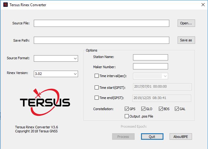
Figure 2.34[]{#_Toc21525 .anchor} Tersus Rinex Converter
The detailed usage of Tersus Rinex Converter refers to section 3.4 Convert Raw Data into Rinex.
2.3.2 Tersus Update
Tersus Update is a tool to upgrade firmware for Tersus GNSS products via serial ports. You can click the icon ![]() in the tool bar or click Tools -> GeoPix or double-click the desktop shortcut
in the tool bar or click Tools -> GeoPix or double-click the desktop shortcut  to launch the software.
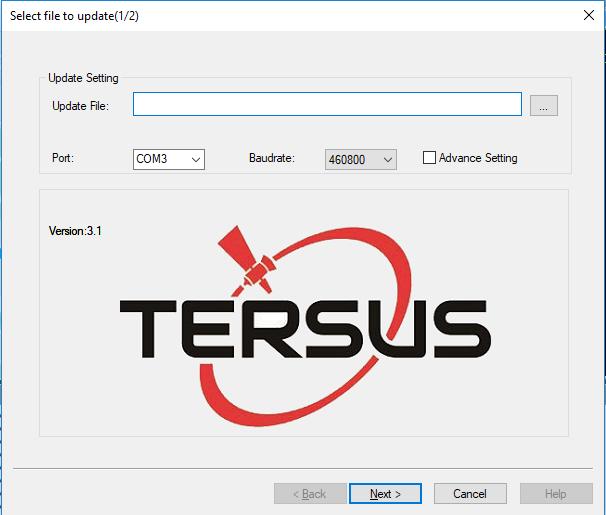
Figure 2.35[]{#_Toc30266 .anchor} Update firmware
Select the upgrade file, select port and baud rate, and click [Next]. After the firmware is upgraded successfully, it will prompt a windows indicating successful update. Click [OK] and [Finish] buttons to close the firmware upgrade windows, the receiver will reset automatically.
Take BX306 board for example, download the latest firmware file from Tersus official website, and put it in the designated folder of your computer. Launch the Tersus Update software, select the firmware file (.bin format), port, baud rate as 115200 and click [Next] for the firmware update. Details refer to section 3.2 in User Manual for BX Series GNSS Receiver.
2.3.3 Tersus Download
Tersus Download is to download data files from internal storage of the receiver to the computer. Double-click the desktop shortcut  to launch the software.
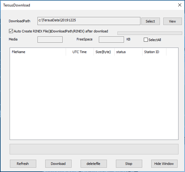
Figure 2.36[]{#_Toc5556 .anchor} Tersus download
Make sure the receiver is connected to the computer through the serial port, click [Refresh] to view the files in the internal storage of the receiver, click [Select] to choose download path, and click [Download] to download files to the designated folder of the computer.
2.3.4 Tersus GeoPix
Tersus GeoPix is a software for processing GNSS observation data collected by UAVs and ground base stations, and tagging EXIF coordinate information of EVENT moment photos. Double-click the desktop shortcut  to launch the software.
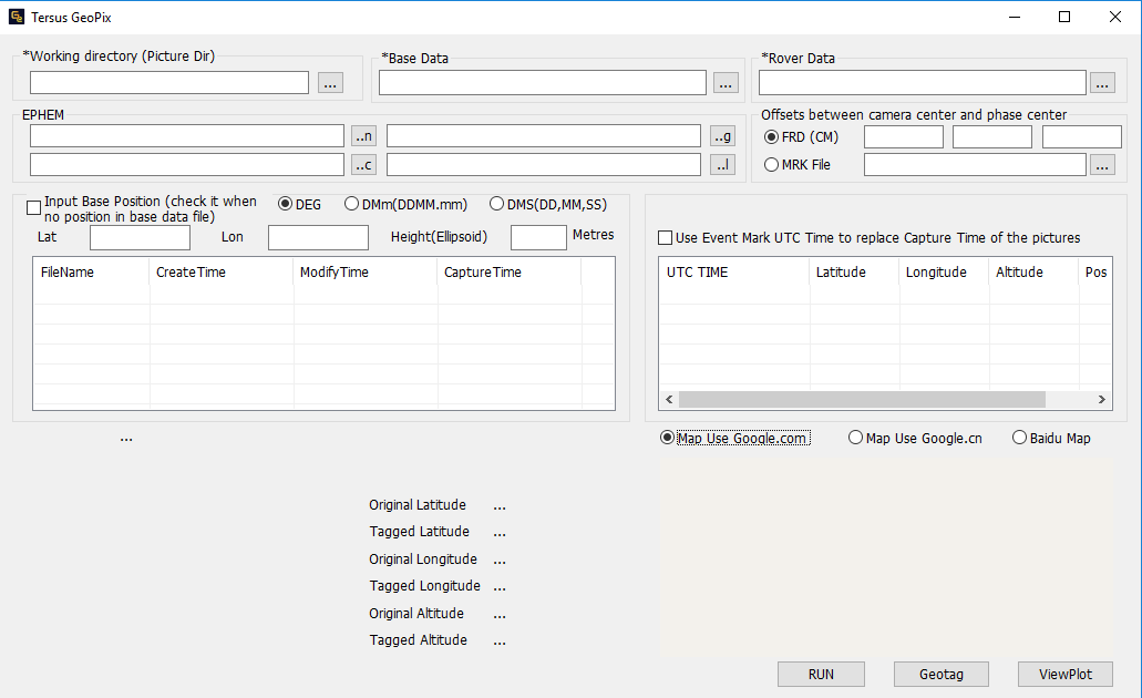
Figure 2.37[]{#_Toc19656 .anchor} GeoPix main interface
The detailed usage of GeoPix refers to the User Manual for UAV PPK Solution which is available on www.tersus-gnss.com/product/uav-ppk-solution.