Software Operations Guide
Software Overview
The TersusAG automatic driving software can be widely used in scenarios such as sowing, plowing, ditching, ridging, spraying, transplanting, land consolidation, harvesting, and other agricultural operations. The development of the software is to integrate multiple operational functions into one software, allowing it to flexibly adapt to various application scenarios.
Running Environment
The hardware environment of the software: Android 11 or above tablet (mobile) Devices. After the software is installed, you can directly click the corresponding icon to enter the software.
Software Performance
-
Response speed of software simple page operation (simple operation of adding, editing, deleting and viewing details), time ≤ 1s.
-
Response speed of complex page operation (complex display, list, configuration and other interfaces), time ≤ 1s.
-
The software can run continuously for 24 hours without lag.
Main Interface
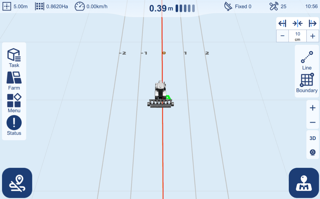
This section will present different functions and buttons for each component of the TersusAG main interface, as depicted below.
Main interface icon introduction:
| > No. | Description | Icon |
+:======:+:======================================:+:==============================================================================================================================================================+
| > 1 | Working width | > ![]() |
|
| > 2 | Work area | > ![]() |
|
| > 3 | Device real-time speed | > ![]() |
|
| > 4 | Offset Error display | > ![]() |
|
| > 5 | GNSS signal status | > ![]() |
|
| > 6 | Satellite number | > ![]() |
|
| > 7 | Time display | > ![]() |
+:======:+:======================================:+:==============================================================================================================================================================+
| > 8 | Line reset / shift | >
|
+:======:+:======================================:+:==============================================================================================================================================================+
| > 8 | Line reset / shift | >  |
|
| > 9 | AB line setting button | >  |
|
| > 10 | Boundary setting button | >  |
|
| > 11 | Zoom in / out button | ![]() |
|
| > 12 | > 2D / 3D view switching button | > ![]() |
|
| > 13 | Camera switch button | > ![]() |
|
| > 14 | Auto-steering button | >  |
|
| > 15 | Manual record button | >  |
|
| > 16 | Task management | >  |
|
| > 17 | Farm management | >  |
|
| > 18 | Menu | >  |
|
| > 19 | System status | >  |
|
Info Bar
The top information bar on the main interface showcases essential details about current operational status.
Implement operating width
Displays the current working width, which is the sum of the implement's width and the width between two adjacent working lines.
Working area
Real-time display of the area covered by the vehicle in auto-steering mode along the AB line. The calculation is based on the speed, time, and width. You can adjust the measurement unit in the settings (refer to the Unit setting under Menu > Advanced Setting).
Device real-time speed
Real-time speed of the vehicle as measured by satellites, displayed in kilometers per hour.
Offset Error display
When in auto-steering mode, this display shows the real-time deviation error of the vehicle from the AB line in centimeters, with arrows indicating the deviation direction.
GNSS signal status
Indicates the current connection status with options such as Single, Float, and Fixed. The number shows the differential delay in seconds. Navigation is only functional when the status shows Fixed. Upon clicking it, swiftly navigate to the GNSS Setting page.
Satellite number
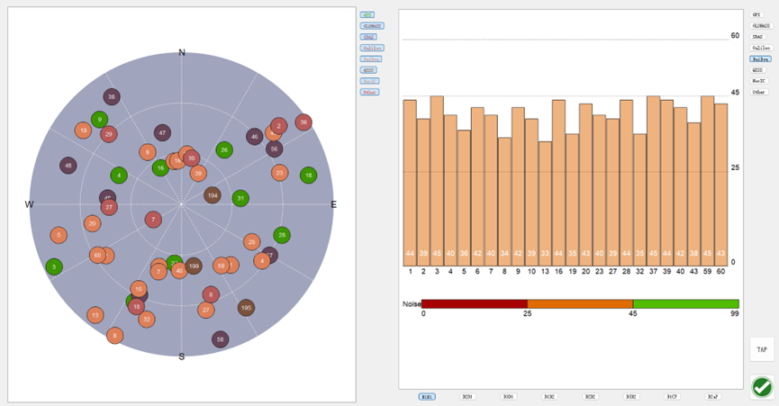
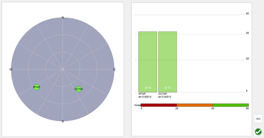
 Indicate the number of nearby visible satellites. Upon clicking the icon, a star map view and a signal-to-noise ratio statistics chart will be displayed.
Time display
Time displayed in the format of hours, minutes. It is allowed to follow the network time(Select Auto in System Setup --- Time) and the satellite time(Select UTC zone in System Setup --- Time).
Operational Area
The central part of the interface prominently presents the map of the operational area, featuring the vehicle's position at the center of the base grid map. Upon setting navigation lines, the corresponding guidance lines near the vehicle will automatically appear on the map.
Guidance Line reset / shift
Shift the AB line left or right according to the user's specified distance. Note that the unit of the distance is centimeter.
Reposition the existing AB line onto the vehicle's current centerline
Zoom in/out
Adjust the current map zoom level.
2D / 3D view switching
2D / 3D view switching button. Switch the vehicle model display mode between 2D and 3D view.
Camera
Turn on/off the camera, with a default of turning off.
Function Bar
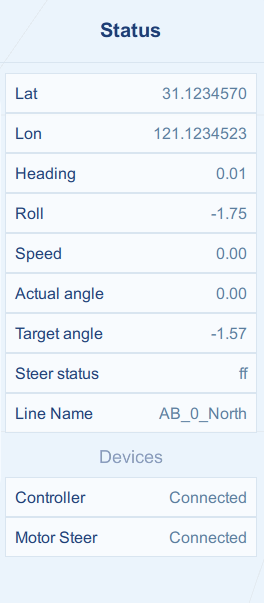
Status
Real-time display of equipment status.
Menu
The various settings of the system include vehicle setting, implement setting, GNSS setting, Calibrations, Auto-steering setting, system setup and troubleshooting.
Farm
Management hub for farms, boundaries and guidance lines.
Task
Management hub for tasks, which record the working statistics.
Guidance line & Boundary Setting
Guidance Line Setting
Within the main interface, users can set the guidance trajectory planned for the vehicle's automatic steering.
Select an existing guidance line from the list, or create new lines, or import files.
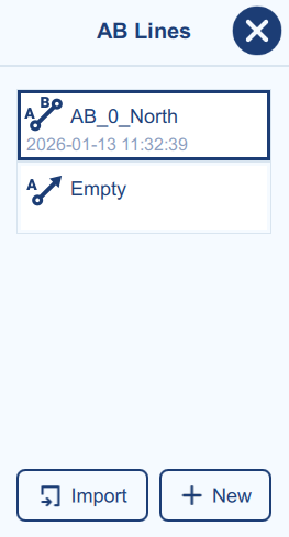
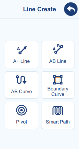
Figure 2‑5 AB Line list (left) and creation (right)
Boundary Setting
Within the main interface, users can set the boundary planned for the vehicle's automatic steering.
Select existed boundary from the list, or create new boundary, or import files.
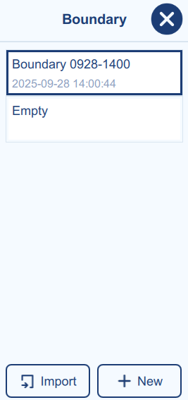
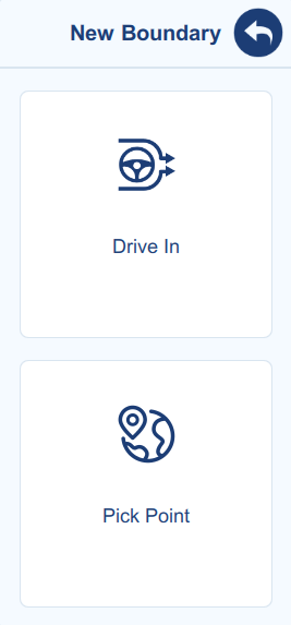
Figure 2‑6 Boundary list (left) and creation (right)
Auto-steering Switch
Button to initiate or pause the auto-steering working mode.
Note:
-
Auto-steering can only commence after setting or importing the AB line.
-
In case of an emergency, manually stop the vehicle.
Button to manually initiate or pause the working area record.
Note:
- If the Auto Record function is enabled from the Control Setting, the button will be hidden.
Menu
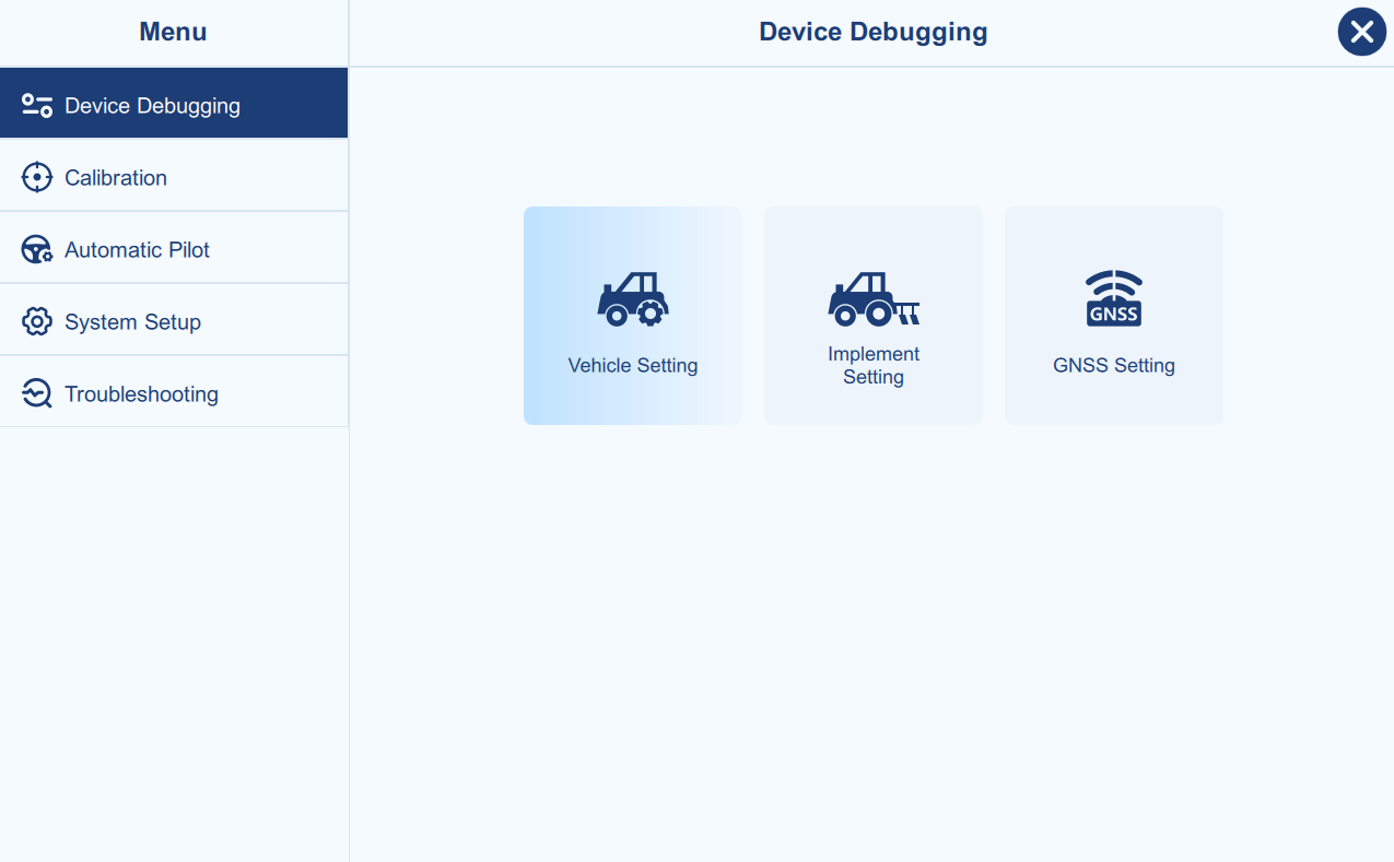
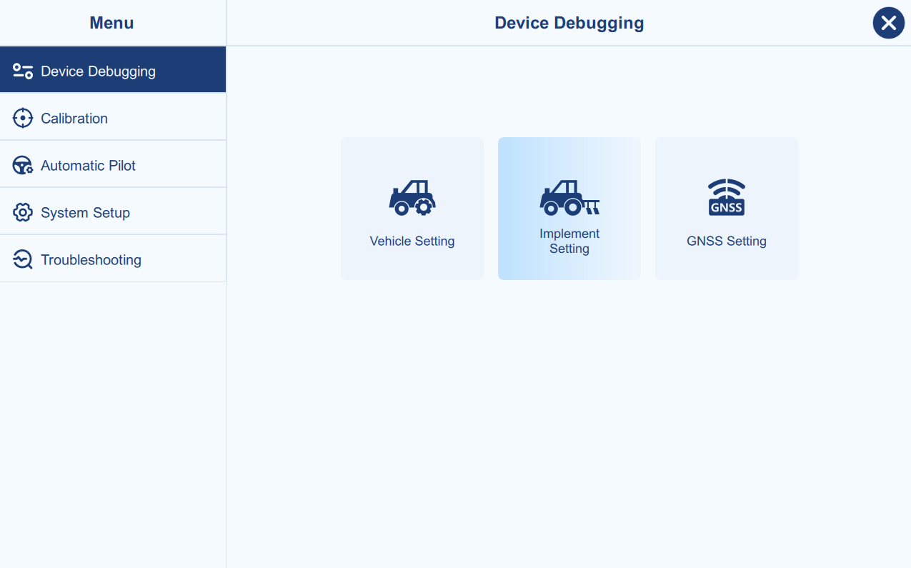
Device Debugging
GNSS Setting
Main Interface → Menu → Device Debugging → GNSS Setting
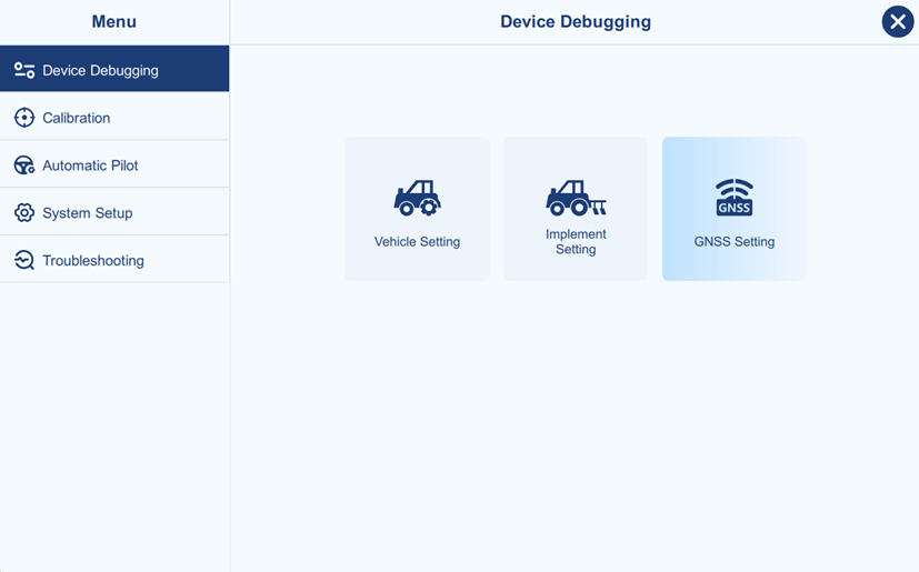
The GNSS setting is for GNSS mode selection, as shown below.
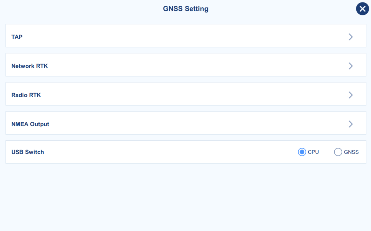
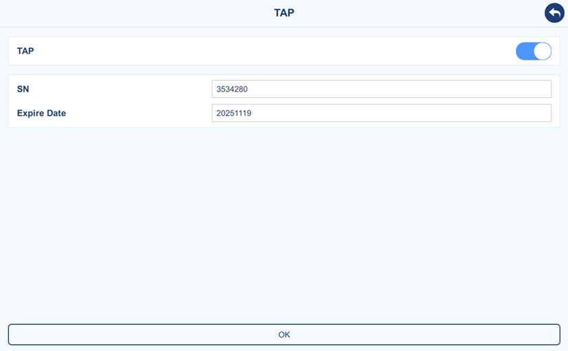
- TAP: Tersus Advanced Positioning, global PPP Service, working without the constraints of a local base station, CORS network, UHF radio or cellular connection. Enable the TAP and click OK to start the TAP service. If the TAP service has expired, please contact support engineer and provide the SN as shown below.
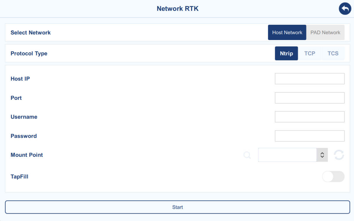
- Network RTK: There are two network selections and three protocol types for options. To access these services, ensure that your area is within the coverage. Input the required parameters---IP, port, username, and login password---associated with your service provider, to get base station connection for RTK. The Tapfill function is to synchronously enable TAP service in the background, and to switch to TAP service once you lost the RTK connection.
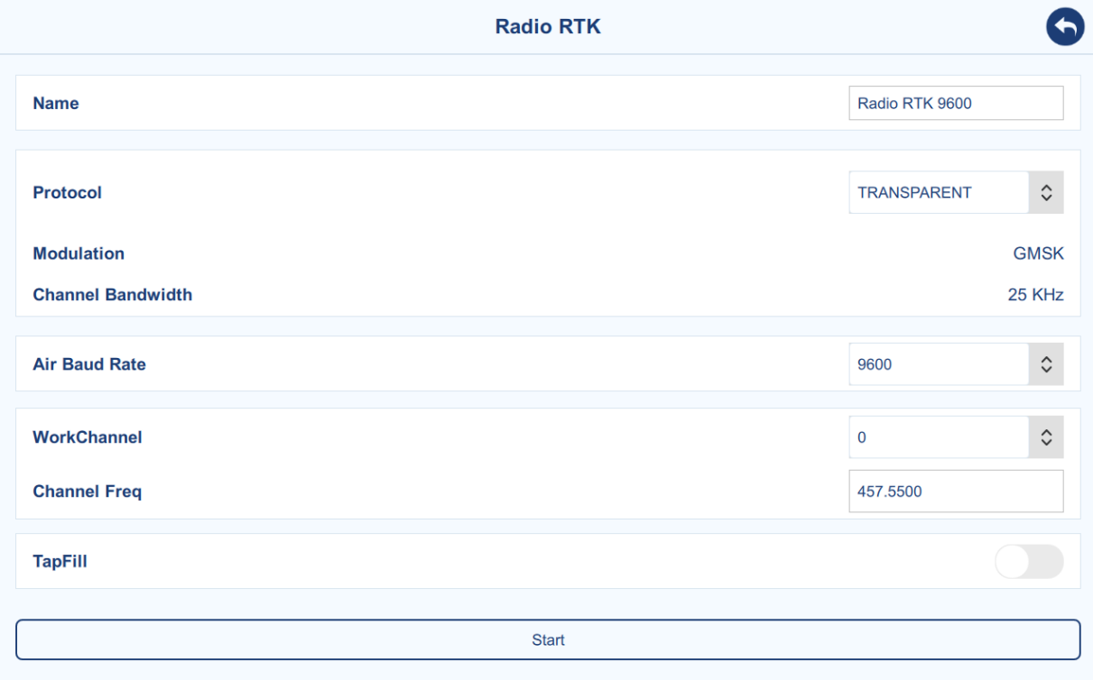
- Radio RTK: TRANSPARENT, TT450, SOUTH, SATEL and TRIMMK3 protocols are supported. 10 preset channels and customized channel are supported. The Tapfill function is to synchronously enable TAP service in the background, and to switch to TAP service once you lost the RTK connection.
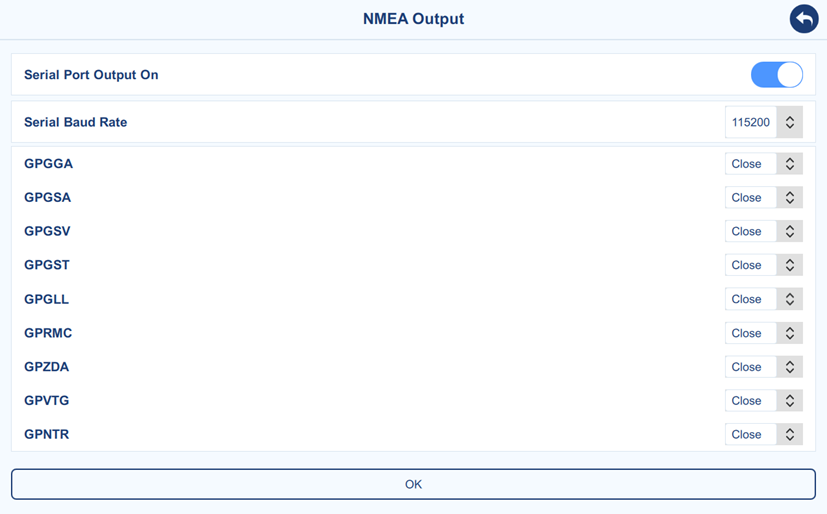
- NMEA Output: Outputting NMEA0183 via serial port is supported.
- USB Switch: This function is for device debugging. If required, support engineer will assist to download system log (witch to CPU) and GNSS inner log (switch to GNSS) from controller type-c port.
Vehicle Setting
Main Interface → Menu → Device Debugging → Vehicle Setting
This section provides functionality for managing information related to the currently selected vehicle and the vehicle list. Users can add, edit, and save details for multiple vehicles. The corresponding parameters for the active vehicle are list on the right side. When the auto-steering system is transferred from one vehicle to another, users can quickly select a previously saved vehicle to ensure a smooth and seamless transition.
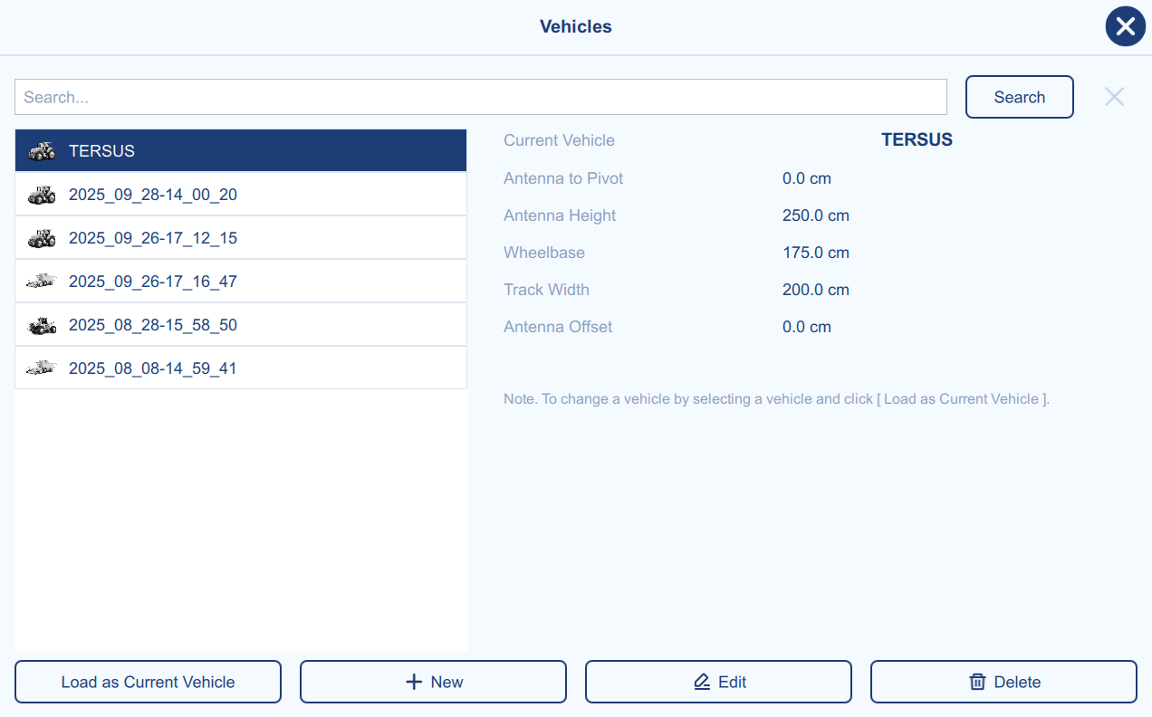
To set a different vehicle as the current vehicle, first select the desired vehicle from the vehicle list, then click Load as Current Vehicle to apply its settings.
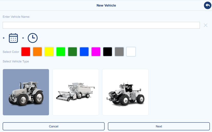
To create a new vehicle, click New to open the vehicle creation page, as shown below. Enter a vehicle name, or click the date/time icon to add additional information. If desired, select a color to customize the appearance of the vehicle model. Select a vehicle type from the list, additional vehicle types will be added in future software updates. Then click Next to go to the next step.
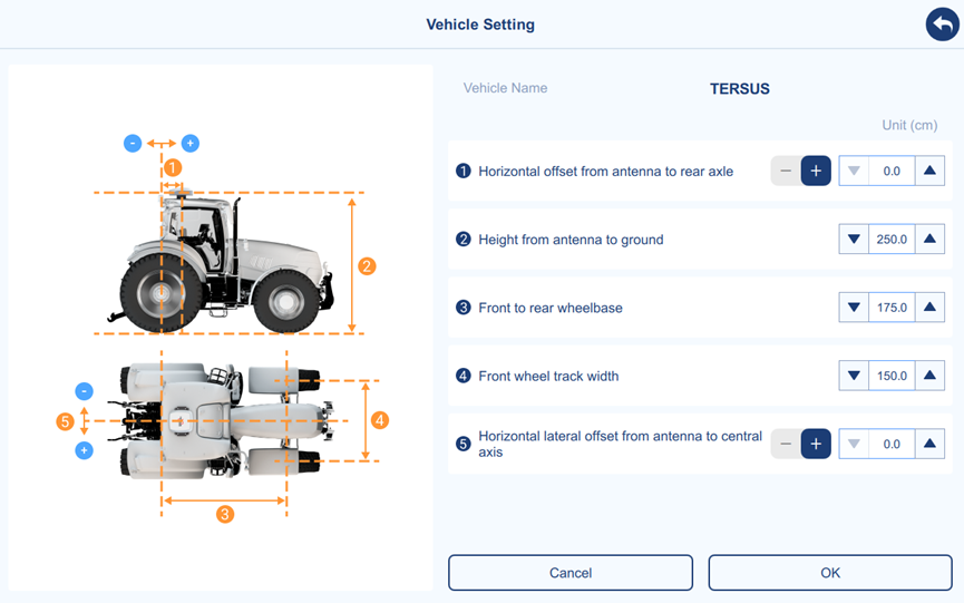
The vehicle parameters include the 5 necessary parameters. It is crucial to accurately measure and input these parameters into the system, with attention to maintaining consistency in units (all parameters should be in centimeter) to ensure correct system operation and optimal performance.
| Parameter | Description |
| 1. | Longitudinal offset of the antenna from the vehicle's rear axle. | | | | | | "-" represents the controller antenna is mounted behind the rear axle of the vehicle. | | | | | | "+" represents the controller antenna is mounted in front of the rear axle of the vehicle. |
| ② | Height from the antenna to the ground. |
| ③ | Wheelbase, the distance between the front axle and the rear axle of the vehicle. |
| ④ | Front wheel track width, the distance between the centers of the left and right front wheels. |
| ⑤ | Lateral offset of the antenna from the vehicle's central axis. | | | | | | "-" represents the controller antenna is mounted on the left side of the vehicle's central axis. | | | | | | "+" represents the controller antenna is mounted on the right side of the vehicle's central axis. |
: Table 2‑1 Description of vehicle parameters
Clicking OK to complete the new vehicle creation, then the new vehicle will be automatically loaded.
Implement Setting
Main Interface → Menu → Device Debugging → Implement Setting
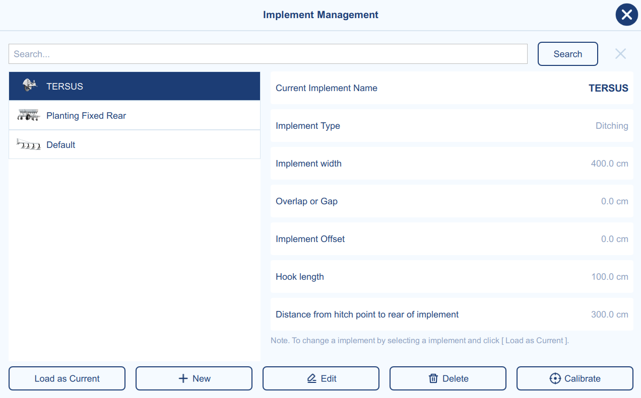
This section provides functionality for managing information related to the currently selected implement and the implement list. Users can add, edit, delete and calibrate for multiple implements.
Please note that, the implement list is bound to the current vehicle. Newly created implements belong to the current vehicle. If you switch to another vehicle, the implement list will also change to correspond to the vehicle.
To set a different implement as the current implement, first select the desired implement from the list, then click Load as Current to apply its settings.
To search an implement from the list, user can input the target name in the search bar. The search function is based on prefix matching and does not support fuzzy search.
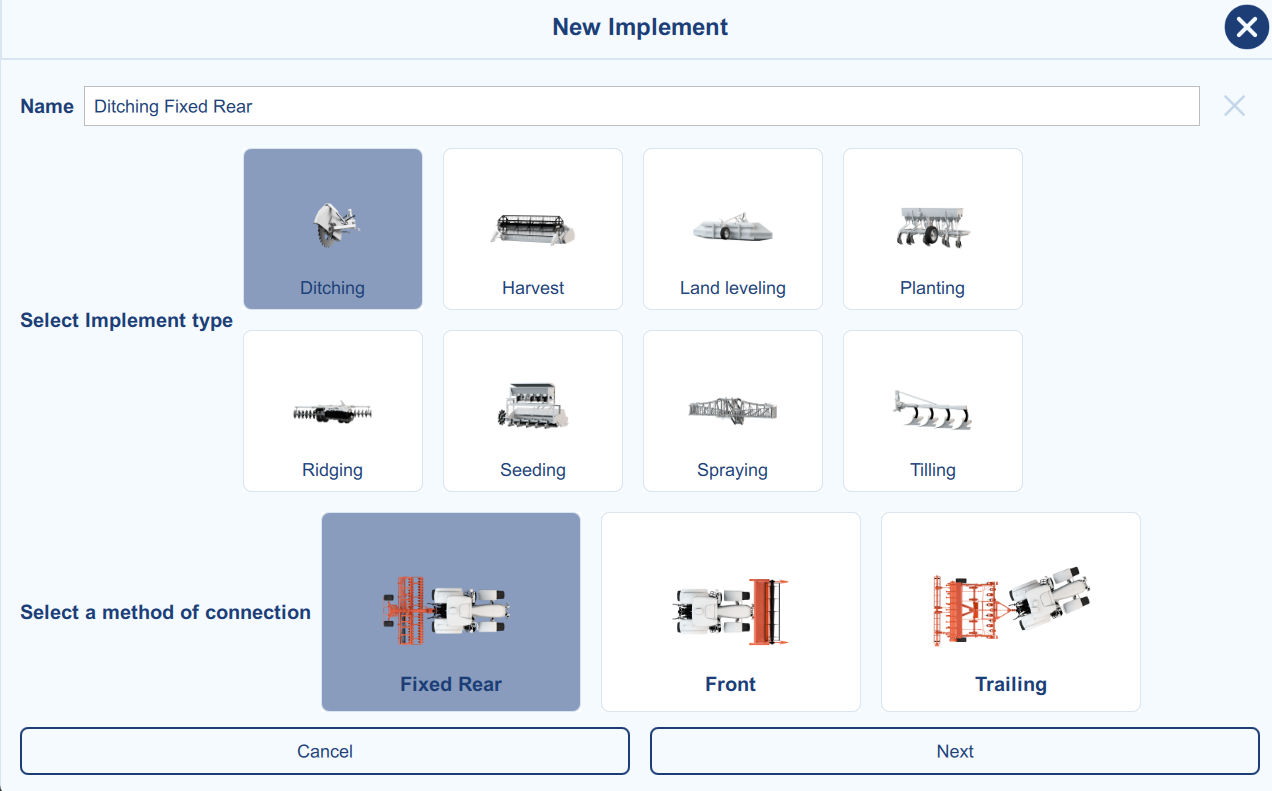
To create a new implement, click New to open the creation page, as shown below. Enter a vehicle name (software gives default name). Select an implement type and connection method. Then click Next to go to the next step.
The vehicle parameters include the 5 necessary parameters. It is crucial to accurately measure and input these parameters into the system, with attention to maintaining consistency in units (all parameters should be in centimeter) to ensure correct system operation and optimal performance.
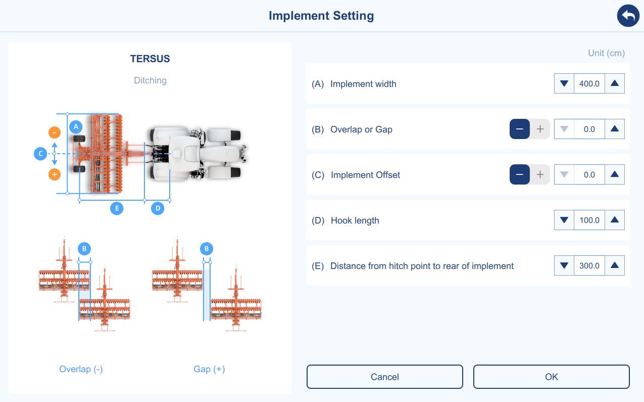
| Parameter | Description | +:=============:+============================================================================================================================================================+ | A | Implement width: The width of the agricultural implement spans from the leftmost to the rightmost units. |
| B | Overlap or Gap: The spacing width between two adjacent lines during operation. | | | | | | "-" represents two adjacent rows are separated by a gap. | | | | | | "+" represents two adjacent rows overlap. |
| C | Implement offset: The distance between the central axis of the implement and the central axis of the vehicle with a selection of left or right offset. | | | | | | "-" represents left offset. | | | | | | "+" represents right offset. |
| D | Hock length: The distance between the rear axle of the vehicle and the hitch point of the vehicle. |
| E | Distance between the rear of the agricultural implement and the hitch point of the vehicle. |
: Table 2‑2 Description of implement setting parameters
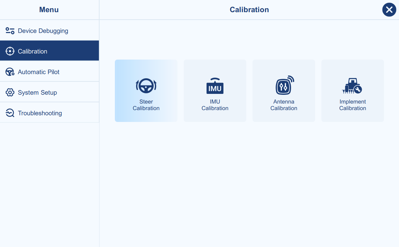
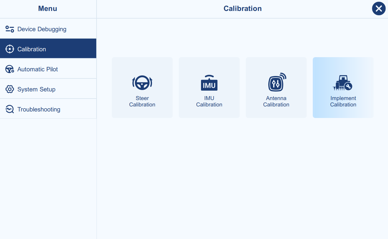
Calibration
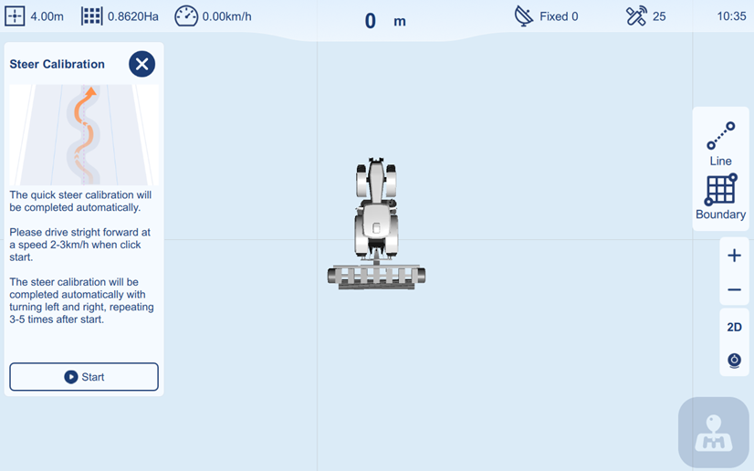
Steer Calibration
Main Interface → Menu → Calibration → Steer Calibration
The steer calibration is to calibrate the steer ratio and coefficient., the process is fully automatic.
Make sure the calibration field is an open, flat and hard-surface ground, drive straight forward at a speed of 2-3 km/h, then click Start.
The calibration process will be completed automatically with repeating 3-5 times turning left and right. Then the "Ackermann" and "Motor Ratio" parameters (in Advanced Setting of Automatic Pilot setting) will be applied according to the calibration result.
IMU Calibration
Main Interface → Menu → Calibration → IMU Calibration
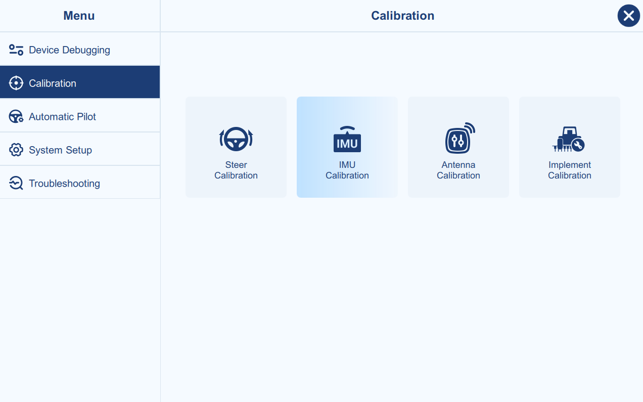
The IMU calibration is to reduce the roll angle error caused by guidance
controller installation.
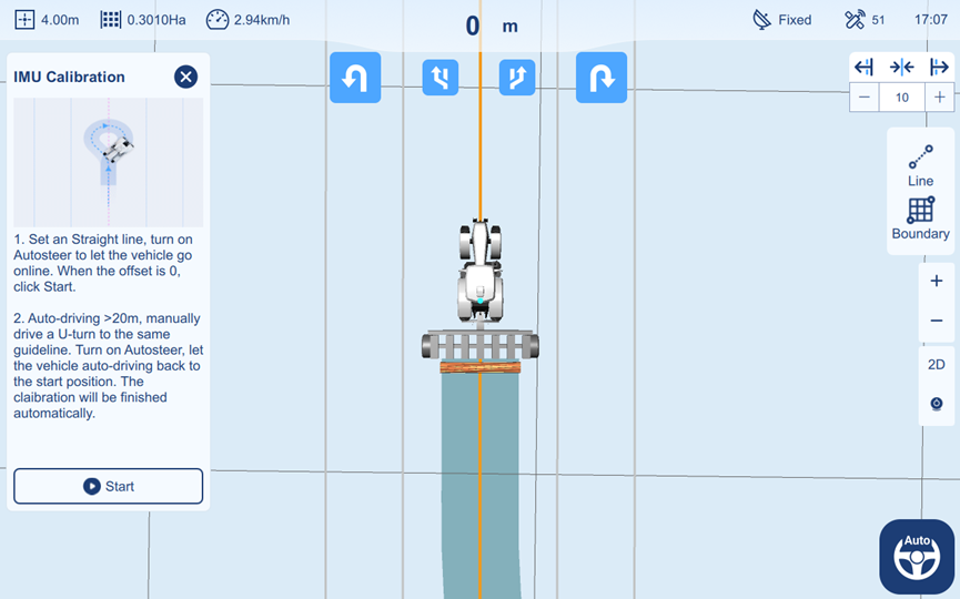
Set a straight line, turn on Autosteer to let the vehicle go online. When the lateral offset is 0, click Start.
Then let the vehicle auto-driving around 20m, software will prompt to make a manual U-turn. Manually drive back to the same line and turn on Autosteer, let the vehicle auto-drive back to the start position. The process will be completed automatically with a prompt.
Antenna Calibration
Main Interface → Menu → Calibration → Antenna Calibration
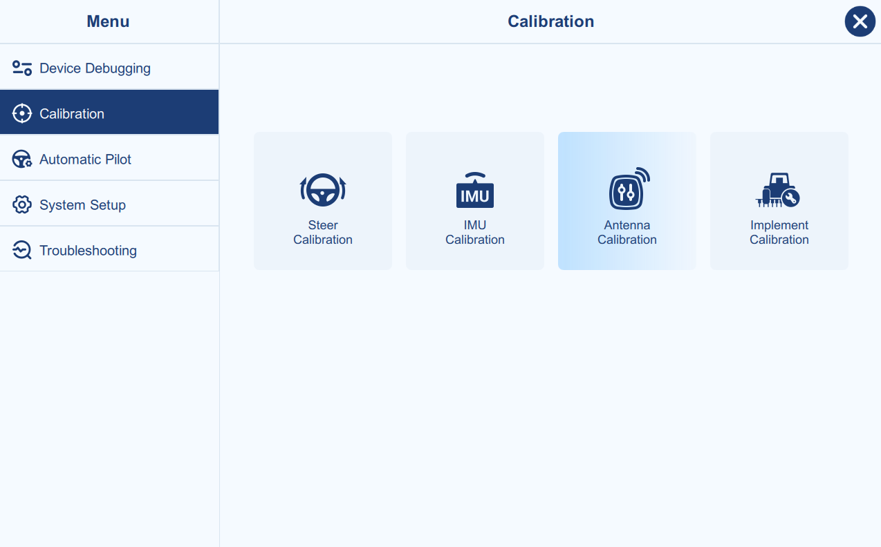
The antenna calibration is to calibrate the deviation caused by guidance controller installation.
In principle, the antenna's central axis should be collinear with the vehicle's central axis. Please accurately measure the horizontal offset of the antenna from the central axis, then this calibration will be not required.
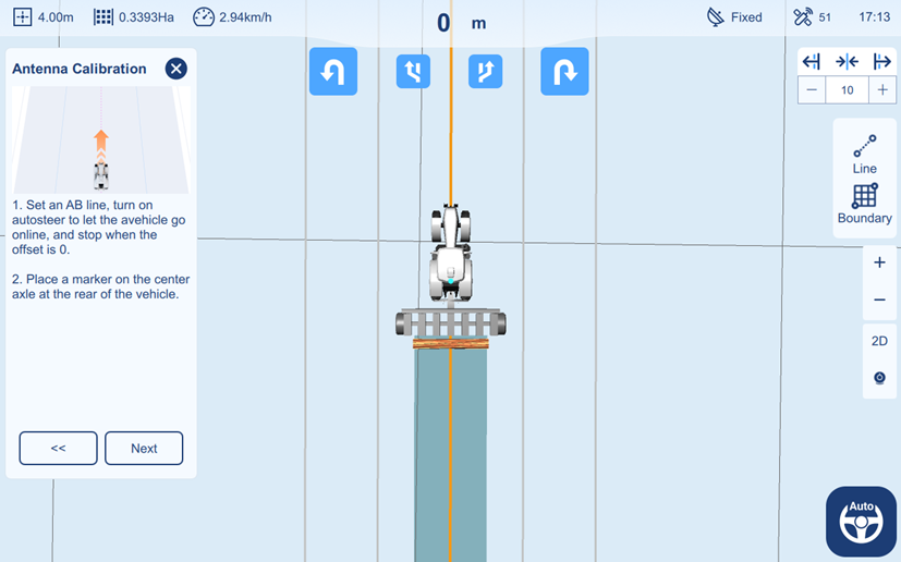
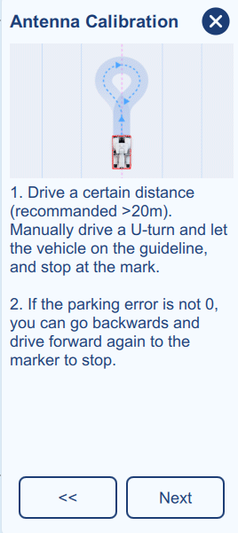
: Figure 2‑27 Antenna Calibration process 2,3
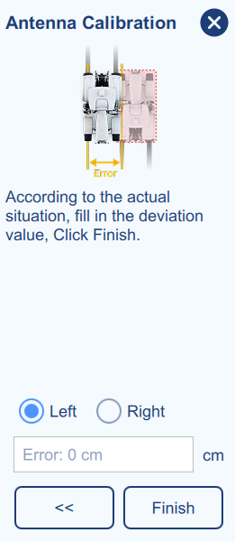
After making a U-turn and returning along the same path in the opposite direction to the original marked position, place a second mark. Measure and compare the deviation between the new mark and the original mark.
When facing the initial driving direction, a new mark positioned to the left of the original mark indicates a left antenna offset; a new mark positioned to the right indicates a right antenna offset.
Implement Calibration
Main Interface → Menu → Calibration → Implement Calibration
After configuring the agricultural implement settings as described above, users can proceed with the initial verification of working line spacing using 3-line method. The primary objective is to test the left and right connecting spacing while navigating through three adjacent working lines as below.
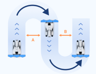
Begin by setting the AB line for the auto-steering mode and proceed with automatic driving for several tens of meters. Subsequently, perform a U-turn, resume navigation, and cover the same distance. Follow this with another U-turn, again covering the same distance. This establishes left and right spacing between the three working lines. Measure the spacing to verify whether the actual values align with the preset spacing values.
When measuring the spacing width, it is recommended to select the middle section with a relatively parallel area between two lines for increased accuracy. This is due to the initial auto-steering adjustment at line starts, resulting in a certain left-right deviation over a distance.
The following explains how to make adjustments (implement correction) in the software, when the actual spacing does not meet the set values. The prerequisite for using the implement correction function is:
-
The parameter settings in the software are accurate, with the entered values matching the actual measurements.
-
The placement of the implement is correct, meaning that, based on actual observation and measurement, the implement is not leaning toward one side.
-
The software adjustment method is used when manual adjustment of the implement is impossible or inconvenient in practical situations.
Automatic Pilot
Control Setting
Main Interface → Menu → Automatic Pilot → Control Setting
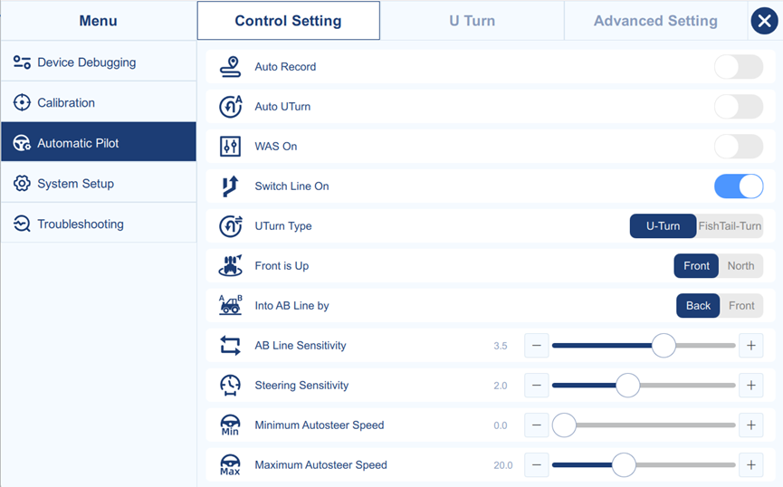
- Auto Record
When Auto Record is enabled, the software will automatically record the work area when auto-driving mode is activated. When Auto Record is disabled, a button will appear on the main screen for the user to manually toggle the recording function on and off.
- Auto U Turn
When Auto U Turn is enabled, the software will automatically generate a U-Turn path when approaching the boundary edge.
- WAS On
When Wheel Angle Sensor (WAS) is connected, enable the "WAS On". The default AG993 system does not require an angle sensor and this option should be disabled.
- Switch Line On
When this function is enabled, the button to switch line left or right will appear on the main page. Clicking the button to switch line left/right will cause the vehicle to automatically switch to the adjacent guidance line on the left/right.
- U-turn Type
The standard U-turn and a fishtail U-turn are available, the default setting is the standard U-turn. When different U-turn types are selected, the parameters on the U-turn settings page will change accordingly.
- Front is Up
If select Front, the front of the vehicle will always point directly to the top of the main page.
If you select North, the top of the main page will always point to true North, and the vehicle's orientation on the page will reflect its actual direction.
- Into AB Line By
The Back and Front represent "the rear of the vehicle" and "the front of the vehicle". The default setting is usually "Back", to avoid overshooting of incoming lines.
- AB Line Sensitivity (1.0-3.5, default 2.0)
Used for Curve Line mode, stability coefficient of autosteer. If the control response is slow, it is easy to make slow turns, then reduce the sensitivity value. If the control range is large, then increase the sensitivity value.
- Steering Sensitivity (1.0-3.5, default 2.0)
Motor steering sensitivity coefficient, if the steering wheel turning too fast, turn the sensitivity lower.
- Minimum Autosteer Speed (0.0-2.0, default 0.0)
Below the minimum speed, Autosteer cannot be engaged.
- Maximum Autosteer Speed (2.0-50.0, default 20.0)
Above the maximum speed, Autosteer cannot be engaged.
- **Maximum Wheel Angle (**5.0--60.0, default 35.0)
Sets the maximum steering angle of the wheels. It is the maximum angle between the center position and the full left or full right wheel position.
U Turn
Main Interface → Menu → Automatic Pilot → U Turn
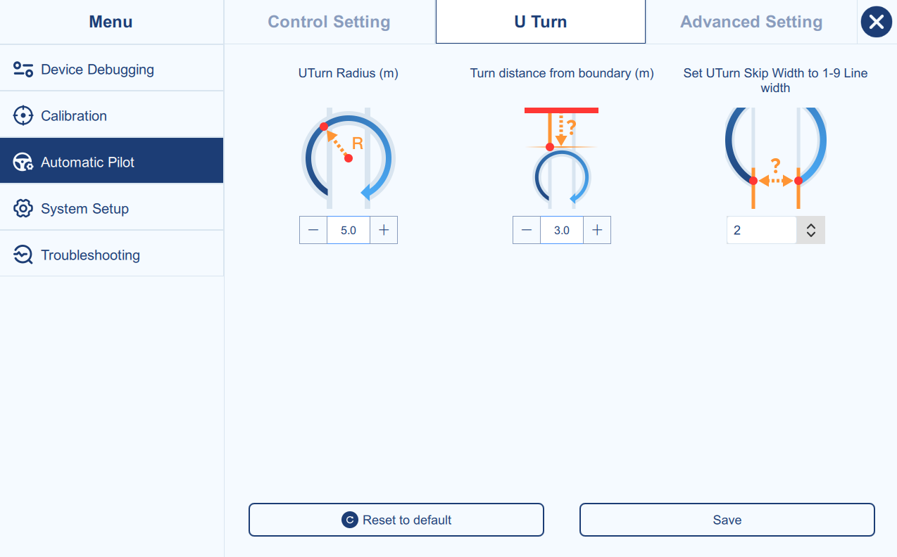
- U Turn Radius
Sets the turning radius for automatic U-turns. Larger values create smoother turns but require more space.
- Turn distance from boundary
Defines the clearance distance between the U-turn path and the field boundary.
- U-turn Skip Width
Sets how many guidance line widths the vehicle will skip after completing a U-turn. The adjustable range is from 1 to 9 line widths.
- Reset to default
Reset all the parameters in U Turn to the default value.
- Save
Save all the parameters in U Turn to the current value.
Advanced Setting
Main Interface → Menu → Automatic Pilot → Advanced Setting
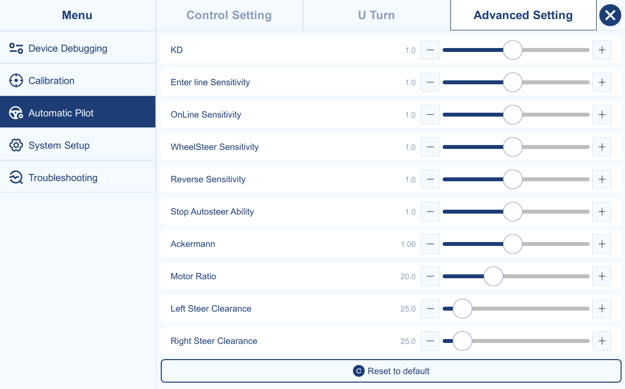
- **KD (**0.1--2.0, default 1.0)
Normally, keep the default value. This parameter affects motor damping and stability. If the steering motor or mounting bracket vibrates because the motor mount is not firm enough, reduce this value to help decrease shaking.
- **EnterLine Sensitivity (**0.1--2.0, default 1.0)
Normally, keep the default value. This parameter controls how aggressively the vehicle enters the guidance line. A lower value makes line entry smoother and uses a smaller entry angle. A higher value makes line entry more aggressive and faster.
- **Online Sensitivity (**0.1--2.0, default 1.0)
Normally, keep the default value. Used in straight-line operation to adjust on-line steering response. If the front wheel response is too slow and the vehicle tends to make gradual bends, increase this value. If the steering correction is too large and the vehicle tends to make small S-shaped oscillations, reduce this value.
- **WheelSteer Sensitivity (**0.1--2.0, default 1.0)
Normally, keep the default value. This parameter adjusts steering sensitivity according to field conditions. In soft soil, where the vehicle tends to turn slowly and make gradual bends, reduce this value. In hard or bumpy field conditions, where the front wheels respond with larger steering movements, increase this value.
- **Reverse Sensitivity (**0.1--2.0, default 1.0)
Normally, keep the default value. This parameter controls autosteer sensitivity while reversing. If the steering response is too slow, increase this value. If the steering correction is too large, reduce this value.
- **Stop Autosteer Ability (**0.1--2.0, default 1.0)
Adjusts the manual override force required to disengage autosteer by turning the steering wheel. A higher value means more force is needed to manually override and stop autosteer.
- **Motor Ratio (**3.0--60.0, Determined by steer calibration)
Normally, do not change this value. It defines the steering ratio between the motor and the steering wheel, and is automatically configured from the steer calibration result.
- **Ackermann (**0.50--2.00, Determined by steer calibration)
Normally, do not change this value. This is the Ackermann steering geometry coefficient and is automatically configured from the steer calibration result.
- **Left Steer Clearance (**10.0--200.0, default 25.0)
Defines the left steering dead zone. It represents the steering wheel free-play angle from the center position until the wheels actually begin to turn left.
- **Right Steer Clearance (**10.0--200.0, default 25.0)
Defines the right steering dead zone. It represents the steering wheel free-play angle from the center position until the wheels actually begin to turn right.
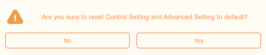
- Reset to default
Reset all the parameters in Control Setting and Advanced Setting to the default value. Please note, if you reset to default, the steer calibration results will also be reset, and new calibration is required.
System Setup
Main Interface → Menu → System Setup
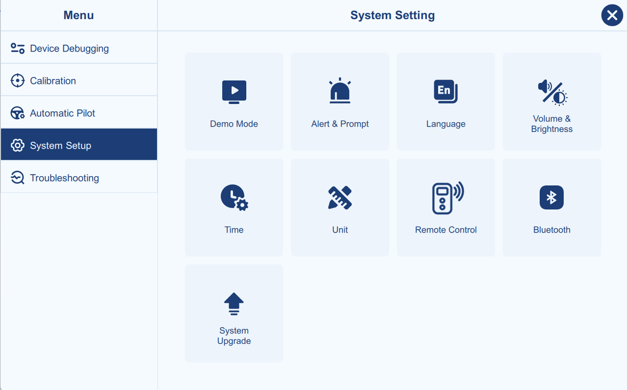
Demo Mode
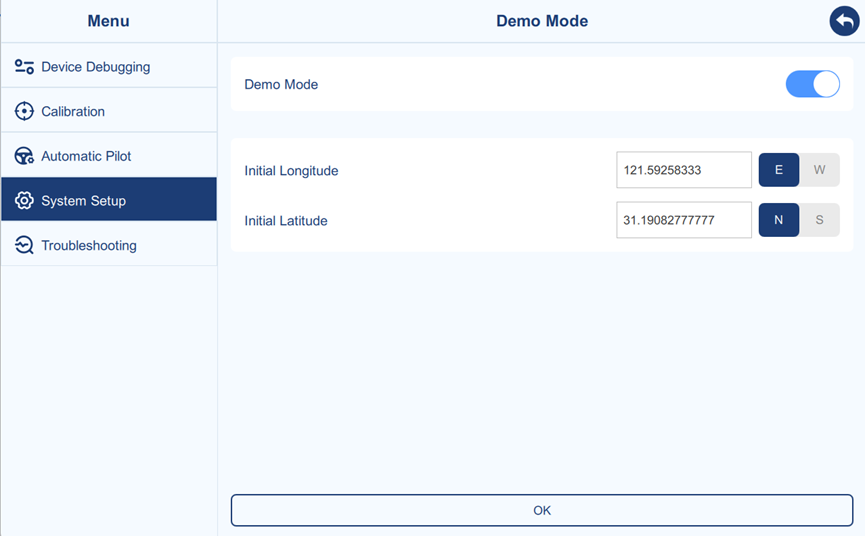
The demo mode switch toggles demo mode on and off.
Clicking OK applies the current page settings.
Initial longitude and initial latitude are used to set the initial position coordinates for the demo mode.
Alert Setting
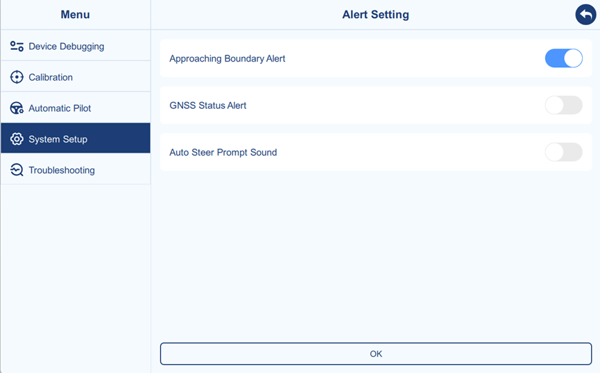
- Approaching Boundary Alert
When the boundary is applied, the software will display a prompt if a vehicle approaches the boundary.
- GNSS Status Alert
When the GNSS status is not fixed, the software will display a prompt.
- Auto Steer Prompt Sound
A prompt sound will play when switching between auto and manual driving modes.
Language
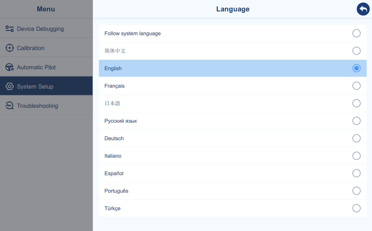
Select different languages as needed. Currently, Chinese, English, French, Japanese, Russian, German, Italian, Spanish, Portuguese, and Turkish are supported.
If your preferred language is not supported, please contact the technical support team.
Volume & Brightness
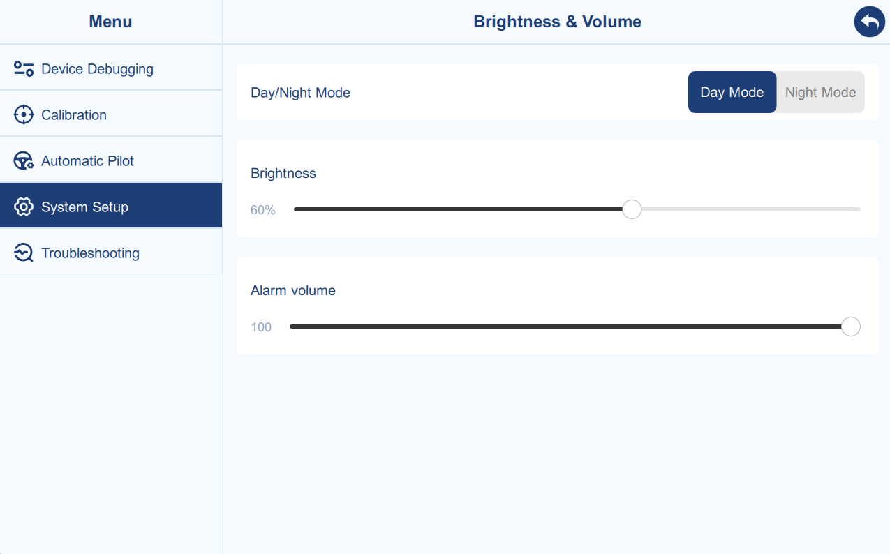
Selecting the default day/night mode will cause the main page to change its color and screen brightness accordingly. Manual adjustment of brightness and volume is also supported.
Time
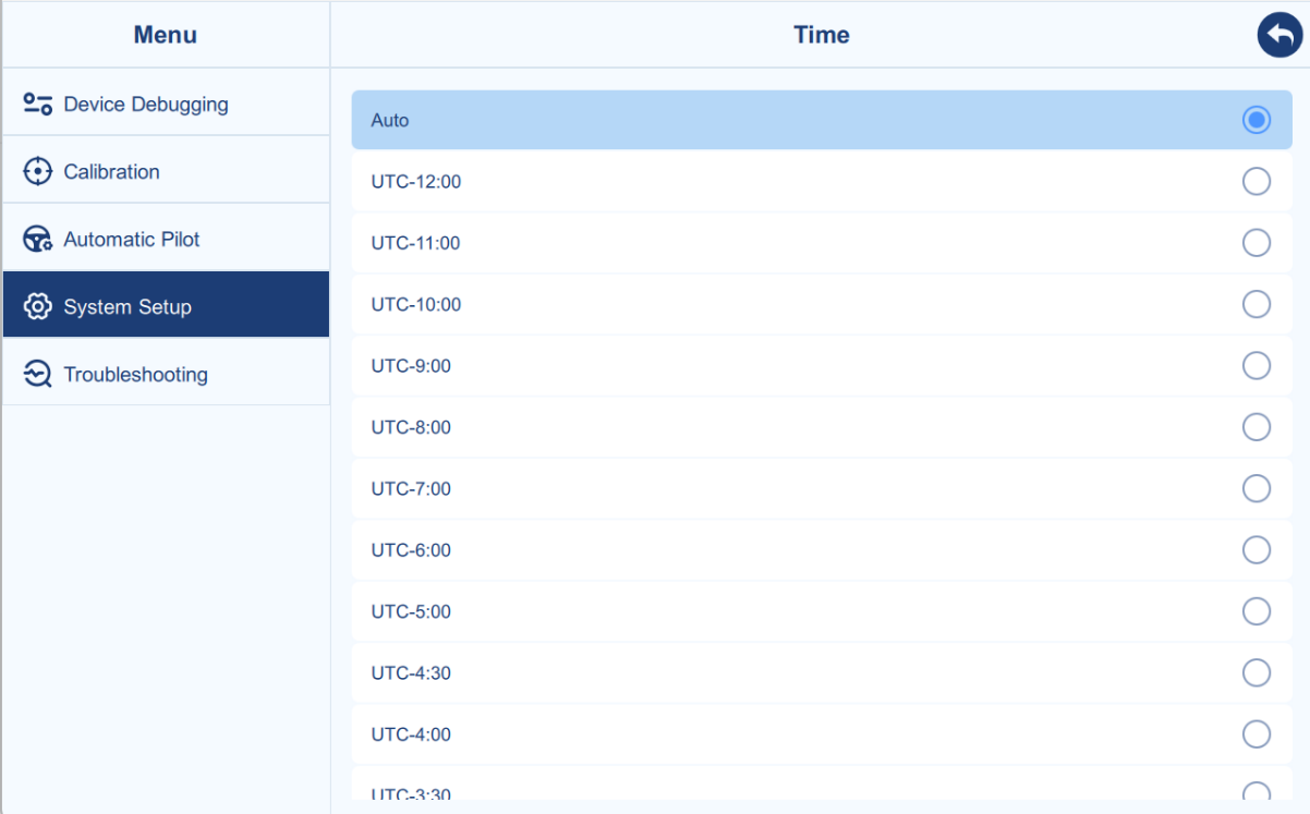
Select the correct UTC time zone, and the software will use the acquired satellite time for calculations. If you select "Auto", the software will directly use the tablet's system time.
Unit
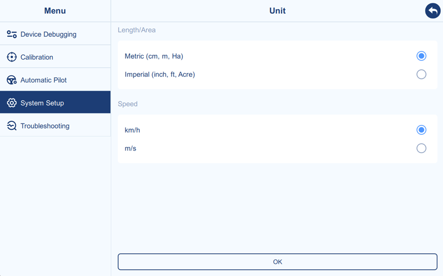
Select the appropriate unit based on user preferences.
Remote Control
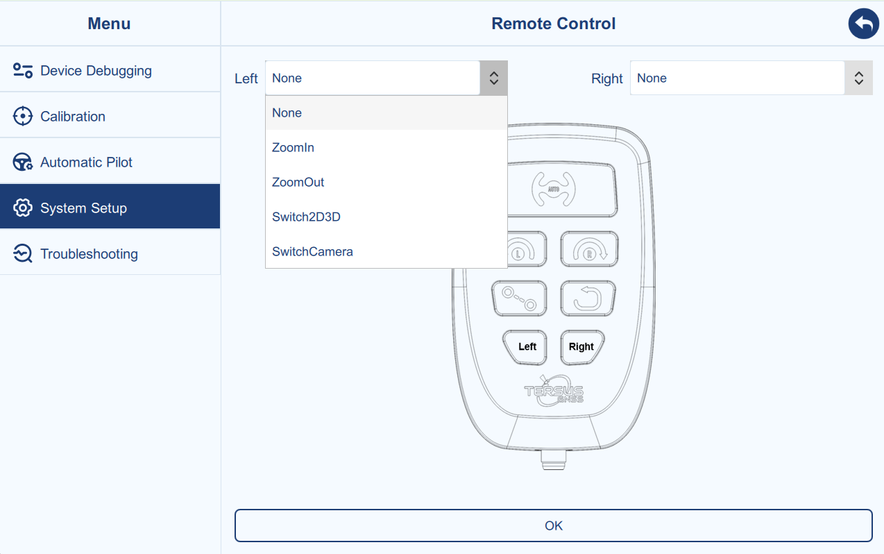
This page allows you to configure the functions of the reserved buttons on the remote control panel (optional accessory). Select the function from the two drop-down menus and click OK.
Bluetooth
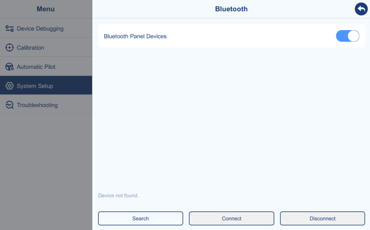
This page is for connecting the Multifunctional Steering Wheel Cover (optional accessory). After turning on the switch, press the "Search" button, select the Bluetooth of the currently used Multifunctional Steering Wheel Cover, and click "Connect".
Please note that "Location" (Setting-Location-Use Location) must be enabled on your tablet before use. Otherwise, the software will not be able to detect Bluetooth.
System Upgrade
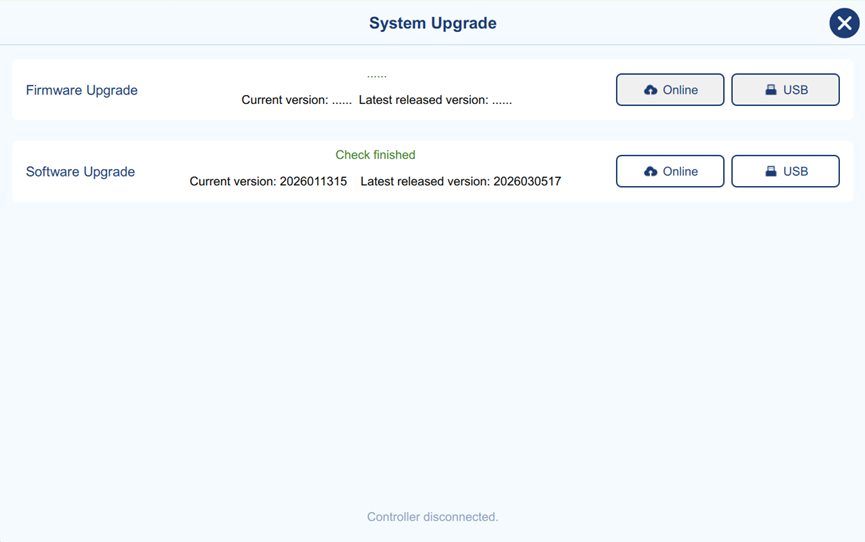
This page displays the current firmware version (controller connection required) and software version, as well as the latest released firmware and software versions on the online server (network connection required).
With a network connection, you can upgrade the server version via online upgrade. Alternatively, you can select a specific firmware/software package version via USB upgrade.
Please note the prompts when upgrading the controller firmware. The controller will automatically restart during the upgrade and automatically re-establish communication with the software after the upgrade is complete. This process usually takes a few minutes, and your patience will be greatly appreciated.
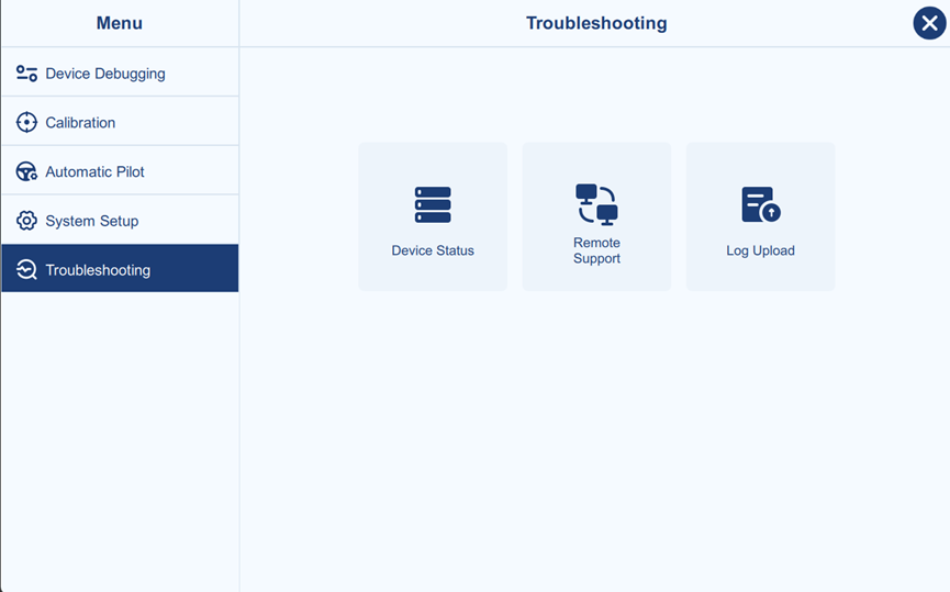
Troubleshooting
Main Interface → Menu → Troubleshooting
Device Status
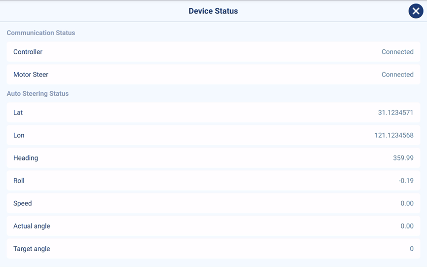
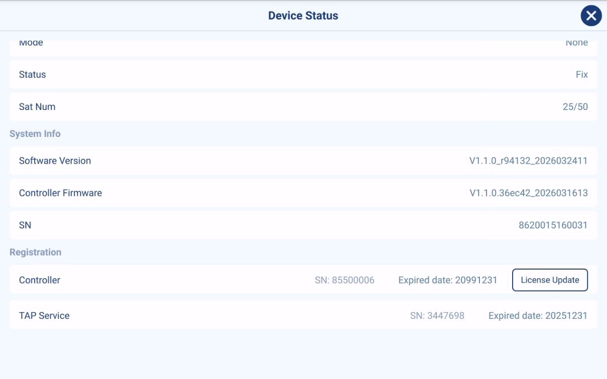
This page lists the current system status information, including communication status, autosteer status, GNSS information, system information, and registration information.
- Communication Status
The communication status includes the communication status of the controller and motor, which can provide a preliminary assessment of the system's connection and communication status. Please note that if the controller communication is abnormal, the motor will also display a communication error message.
- Auto Steering Status
Including positioning and attitude information, etc.
- GNSS Info
Including GNSS solution status and number of satellites, etc.
- System Info
Including current software version, firmware version and tablet serial number.
- Registration
Including controller and TAP service registration. "License Update" can complete the online update of the controller registration.
Remote Support
Please use AnyDesk and contact with support team for remote support.

Log Upload
Please upload corresponding log as instructed by technical support.
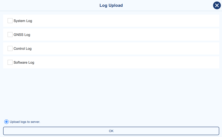
Notes:
-
Selecting "Upload logs to server" will upload the selected logs to the server when the internet connection is established, allowing technical support engineers to view them directly. Upload time will largely depend on network conditions.
-
If "Upload logs to server" is not selected, the selected logs will be downloaded directly to the tablet. The software will then display the download path in a pop-up window, allowing the user to copy and send it to technical support engineers.
Farm
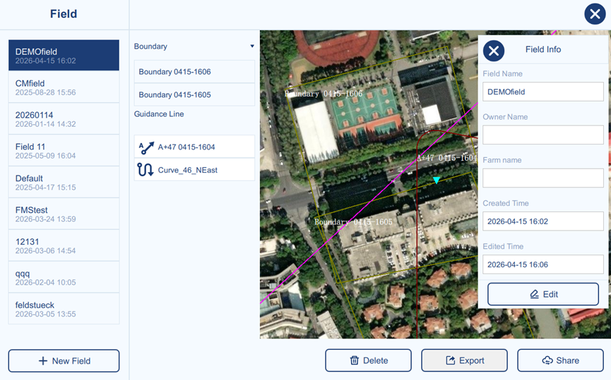
The Farm page provides an overview of all fields on the current device. Each field contains its corresponding boundaries and guidance lines, which can be viewed from the list and previewed on the map. The selected boundary or guidance line is highlighted in the map preview for quick reference. Users can also manage field data with functions including Edit, Delete, Export, and Online Share.
New Field
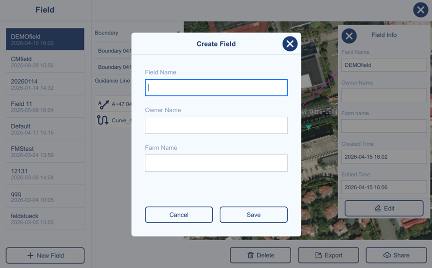
Create a new field by entering the field name, owner name, and farm name. Click Save to confirm or Cancel to close the window.
After saving, the field information can be updated through Edit.
Delete Field
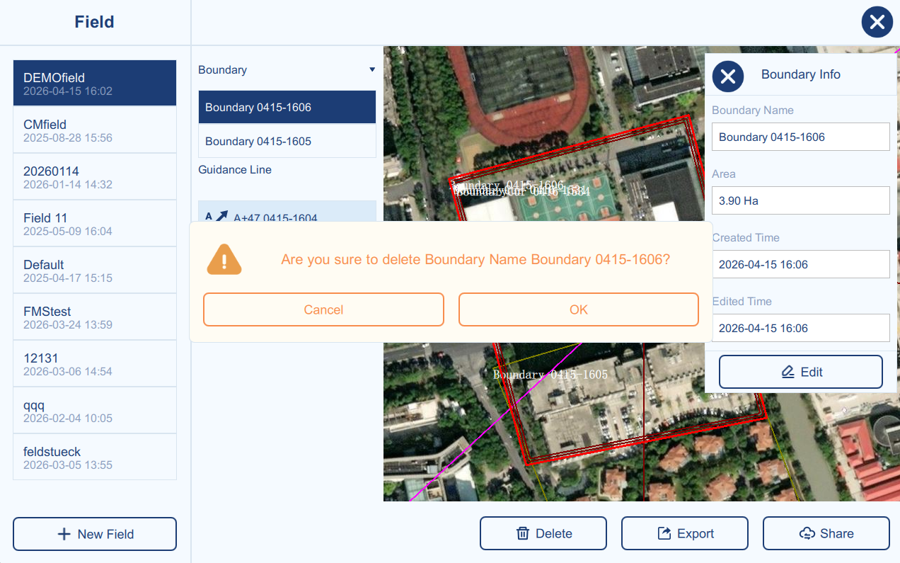
Deletes the currently selected item (Field/Boundary/Guidance Line) from the list.
Export
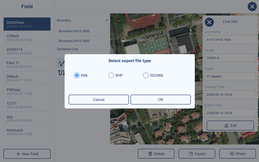
This function allows the selected boundary or guidance line to be exported in the desired file format and saved locally or to a USB drive for transfer to other devices.
Share
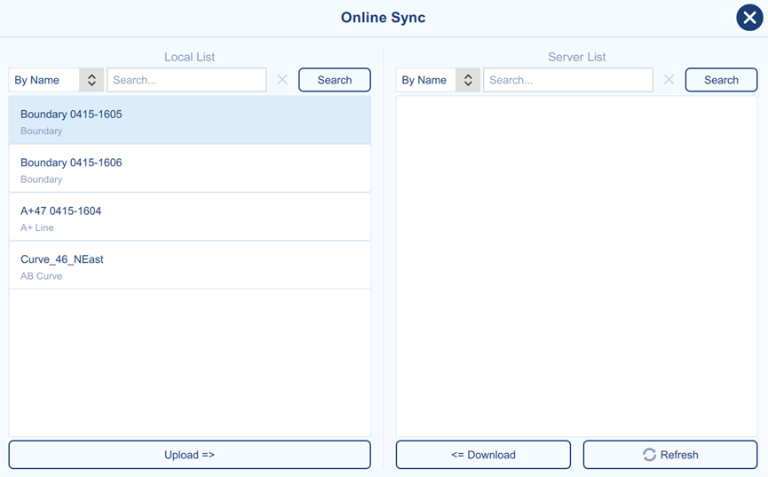
The Online Share page is used to synchronize boundaries and guidance lines between local storage and the cloud server. The Local List on the left shows data stored on the current device, while the Server List on the right shows data available online.
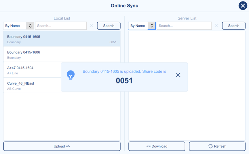
Users can select a local item and upload it to the cloud, and the system will return a share code that can be provided to other users for downloading. Users can also search from the server list by name or share code and download the selected data to the local device.
Task
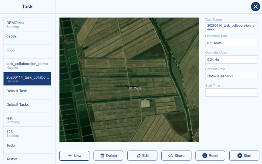
The Task page displays the list of tasks stored on the current device. Each task mainly records the operation statistics generated when the task is performed, such as operation time and operation area. After a task is selected, its coverage can be previewed on the map. This page also supports task management functions such as New, Edit, Delete, Online Share, Reset, Start, and Stop.
New Task
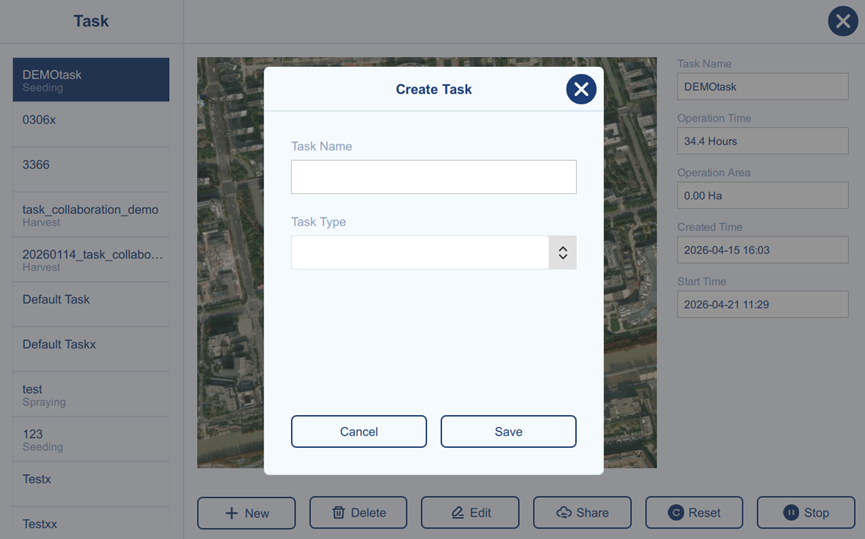
Create a new task by entering the task name, task type. Click Save to confirm or Cancel to close the window.
After saving, the task name can be updated through Edit.
Delete Task
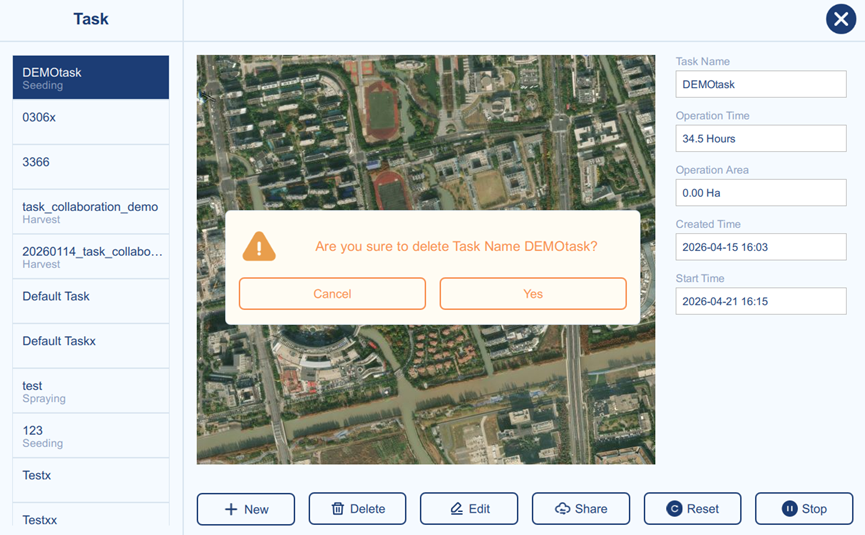
Deletes the currently selected task from the task list.
Share
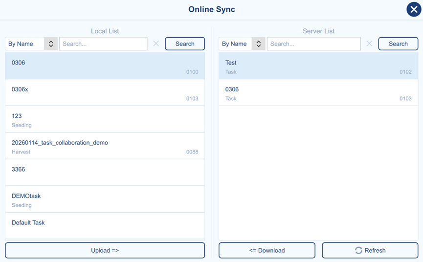
The Online Share page is used to synchronize tasks between local storage and the cloud server. The Local List on the left shows tasks stored on the current device, while the Server List on the right shows tasks available online.
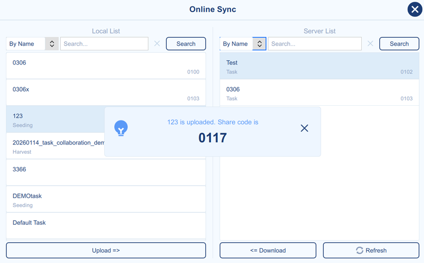
Users can select a local task and upload it to the cloud, and the system will return a share code that can be provided to other users for downloading. Users can also search from the server list by name or share code and download the selected task to the local device.
Once a task is uploaded, any new records of this task will be automatically synced to the cloud server. If other users are utilizing this task, they can also synchronize records generated by those other users. The timeliness of synchronization will be affected by network conditions.
Reset
Reset will clear the working records logged in the current task and automatically stop the task.
Start/Stop
When a task is selected, any work records generated are logged to that specific task only after the task has been started. It is not allowed to record work area if the task has not yet been started. Task can also be stopped manually.
Proprietary Notice
All Information in this document is subject to change without notice and does not reflect the commitment on Tersus GNSS Inc. No part of this manual may be reproduced or transmitted by all means without authorization of Tersus GNSS Inc. The software described in this document must be used in terms of the agreement. Any modification without permission from Tersus GNSS Inc. is not allowed.