Introduction
This chapter includes overview, receiver features, and devices in the package.
Overview
The Tersus AG993 Auto-Steering System is an automatic steering system which uses integrated guidance controller and high-torque motor control steering wheel. It integrates the advantages of convenient installation, large torque, high precision, low noise, low heat, and quick debugging. It is suitable for various applications of tractors, harvesting machines, plant protection machinery, rice transplanters and other agricultural models.
The system includes a highly integrated guidance controller, a display tablet and an electric steering wheel. It provides satellite-based Precise Point Positioning (PPP) service with global coverage. It controls the vehicle and co-operates with/without a base station to form a whole machine control system for agriculture applications. It can be widely used for sowing, cultivating, trenching, ridging, spraying pesticide, transplanting, land consolidation, harvesting and other work scenarios.
Devices in the package
The devices in the package may vary according to the customer requirement. Here describes the major parts in the package.
| AG993 with Basic Accessories |
+:=======================:+:============================================:+:===========================================================================================================================================================:+
| 1 | GC30 Guidance Controller | 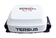 |
|
| 2 | TC120 Tablet |  |
|
| 3 | TES30 Electric Motor | 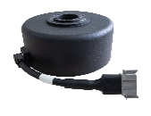 |
|
| 4 | Main Cable | 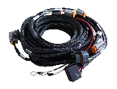 |
|
| 5 | Steering Wheel | 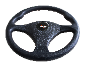 |
|
| 6 | Camera | 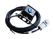 |
|
| 7 | Power Switch Mount | 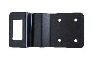 |
|
| 8 | Motor Bracket A |  |
|
| 9 | Motor Bracket U | 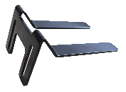 |
|
| 10 | Tablet Bracket |  |
|
| 11 | Zip Tie | 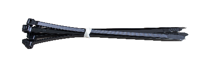 |
|
| 12 | Type-C to USB Converter |  |
|
| 13 | Spline | 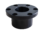 |
|
| 14 | Screw Pack |  |
|
| 15 | Warranty Card |  |
|
| Optional Accessories |
| 16 | Radio Antenna |  |
|
| 17 | Steering Wheel Knob | 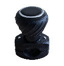 |
|
| 18 | Wheel Angle Sensor | 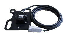 |
|
| 19 | Remote Control Panel with Cable | 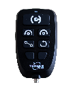 |
|
| 20 | Remote Control Panel Cable |  |
|
| 21 | Multifunctional Steering Wheel Cover (400mm) | 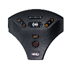 |
|
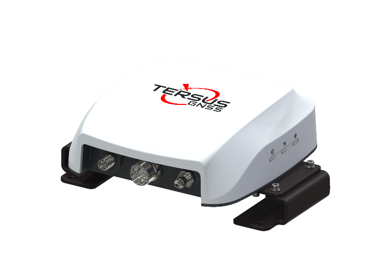
GC30 Guidance Controller
The Tersus GC30 Guidance Controller is a highly integrated, multi-constellation high-precision GNSS receiver that provides centimeter-level accuracy. It not only supports RTK positioning but, more importantly, comes equipped with TAP (Tersus Advanced Positioning), a satellite-based precise point positioning service.
When integrated into AG993 Auto-Steering System, GC30 guidance controller connects to the tablet via main cable, enabling the system to directly receive RTK corrections from the local RTK base station or CORS.
With TAP service, the AG993 Auto-Steering system achieves centimeter-level high-precision positioning even in areas with poor network coverage, such as oceans, deserts, mountains, high altitudes, etc. After 3-5 minutes convergence time, less than 5 cm accuracy can be achieved.
Controller Features
- Supports multiple constellations & frequencies
-
GPS L1 C/A, L2C, L2P, L5C
-
GLONASS L1 C/A, L2 C/A
-
BeiDou B1I, B2I, B2a, B3I
-
Galileo E1, E5a, E5b
-
QZSS L1 C/A, L2C, L5
-
L-Band
-
Supports RTCM2.3/3.x, CMR, CMR+ corrections.
-
Solution update rate can be 20Hz.
-
Inertial Measurement Unit (IMU) supported.
-
Internal radio supported.
-
Internal Bluetooth, Wi-Fi, Cellular module supported.
-
IP67 for waterproof & dustproof, work reliably in harsh condition
Ports and Lights
The GC30 guidance controller has 3 ports and 3 lights as shown below.
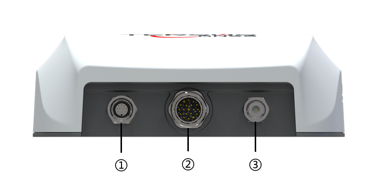
-
COM1 port: Connect to Tablet.
-
COM2 port: Connect to Motor, Remote Control and WAS.
-
RADIO port: Connect to external radio antenna.

| NO. | LED | Description | +:=======:+:==========:+:===========================================================================================================================================+ | ④ | Status | ON: GC30 is booting, or in Fixed solution status. | | | | | | | | Flash(2Hz): GC30 is in Float or DGPS solution status. | | | | | | | | Blink(5s): GC30 is in single solution status. |
| ⑤ | Correction | OFF: GC30 receives no correction. | | | | | | | | Flash(1Hz): GC30 is receiving correction. |
| ⑥ | Satellite | OFF: GC30 receives no satellite. | | | | | | | | Flash: GC30 receives satellites. The number of quick flash sequence represents the number of satellites. (2s between each flash sequences) |
: Table 1‑1 Description of LED status of GC30
TC120 Display Tablet
The TC120 Control Tablet is shown as below.

Tablet Features
-
Powerful hardware: 8-core CPU, 2.0GHz, 3GB RAM and 32GB ROM.
-
Integrated High-Precision GNSS: Embedded 4G modem, Bluetooth, and Wi-Fi module.
-
User-friendly operating system: Android 11.
-
Versatile communication interfaces: CAN Bus, Serial, Ethernet, a waterproof USB interface, and more, catering to diverse application requirements.
-
Rugged design: IP67 protection, offering durability and resistance in challenging environmental conditions.
-
Wide Voltage Input Range: Supports a voltage input range of 9-36VDC, allowing it to withstand vehicle ignition without a restart, along with overcurrent and overvoltage protection.
-
Compact, fanless design: a well-engineered internal structure for efficient heat dissipation.
-
High-resolution touchscreen: 10.1-inch capacitive touchscreen, a resolution of 1280 × 800, brightness of 600 nits, ensuring high visibility even in bright conditions.
Button and Port
BUTTON: Power button, short press to lock screen, long press to power off and restart.
PORT:
PIN Definition Direction
  1                 B+                  Input

  2                 B-                  Input

  3                ACC                  Input

  4               CAN1_H             BI direction

  5               CAN1_L             BI direction

  6            12V_OUTPUT1              Output

  7            12V_OUTPUT2              Output

  8                GND                    /

  9              RS485_A             BI direction

 10              RS485_B             BI direction

 11               CAN2_H             BI direction

 12               CAN2_L             BI direction

 13            12V_OUTPUT3              Output

 14             RS232_TX1               Output

 15            GPIO_INPUT2              Input

 16              CAMERA_1               Input

 17             RS232_RX2               Input

 18              RJ45_TX-               Output

 19              RJ45_RX-               Input

 20             RS232_RX1               Input

 21            GPIO_INPUT1              Input

 22              CAMERA_0               Input

 23            CVBS_PWR_12V             Output

 24             RS232_TX2               Output

 25              RJ45_TX+               Output
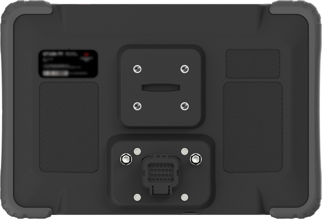
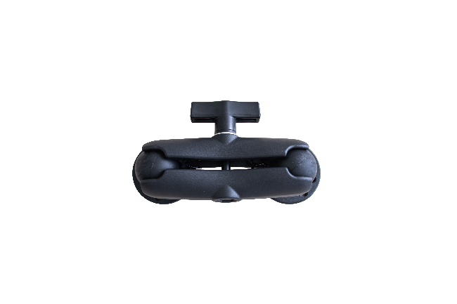
Tablet Bracket
The tablet bracket ensures a secure fixation of the tablet in the driver's cabin, allowing the driver to operate it at the desired angle with convenience.
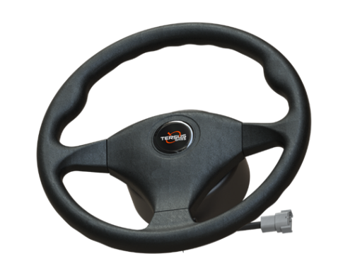
TES30 Electric Motor Wheel
The TES30 electric motorized steering wheel is designed for optimal performance and user convenience. Equipped with a stable and high-torque motor, it ensures nimble reactions for precise steering control. Its user-friendly design facilitates easy installation and maintenance, making it compatible with most tractor types. Experience optimal performance with low noise, minimal heat emission, and exceptional steering accuracy. With an IP55 protection rating, this electric motor steering wheel stands out for its durability and resilience in various environmental conditions.
Spline
During the installation of the electric motor wheel onto the vehicle, it is essential to use a spline that matches a corresponding set on the interior of the steering wheel hub. This spline connection ensures proper alignment and secure attachment, playing a crucial role in maintaining accurate steering control and preventing slippage during operation.
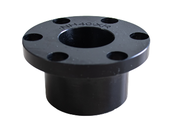
Figure 1‑8 Spline
Motor Bracket
The motor bracket ensures a secure attachment of the electric motor to the wheel hub for the steering wheel.
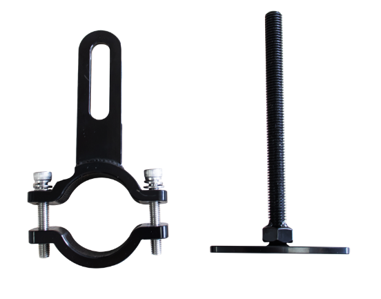

Figure 1‑9 Motor Bracket A & U
Camera
Camera is mounted on the front or rear of vehicle to get view of surroundings, connects to camera port of the main cable via camera extension cable.
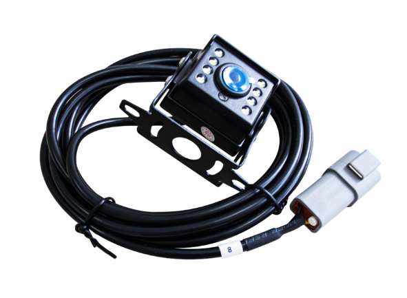
Figure 1‑10 camera
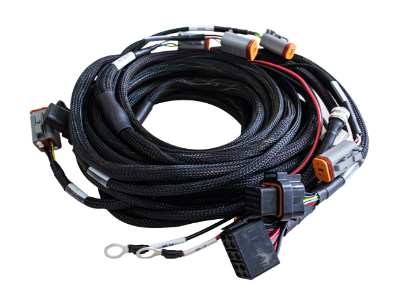
Main Cable
This main cable connects every part of the system, supplying power and transmitting data.